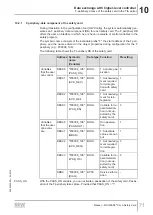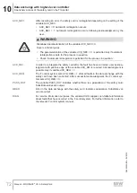
8
Electrical installation
Safe digital outputs (F-DO.)
Manual – MOVISAFE
®
CS..A Safety Card
57
8.6.4
Ohmic loads
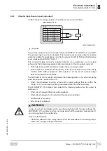
Lamps are examples of ohmic loads.
•
Lamps can be connected for display purposes. Note that an increased cold current
flows when incandescent lamps or halogen lamps are switched on. The cold cur-
rent must not exceed the permitted output current pursuant to DIN EN 61131-2.
8.6.5
Information about line diagnostics and test pulses
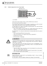
Short voltage pulses are added to the output signals to monitor the cabling. This
means the output voltage is interrupted briefly (pulsed). The maximum duration of the
interruption can be set in the F-DO parameter
Test duration
. The required duration of
test pulses is determined by the capacitances in the connected load, which affect the
line diagnostics.
For the protective separation of MOVISAFE
®
CS..A with a maximum of 10
MOVIDRIVE
®
modular and MOVIDRIVE
®
system units, a test pulse duration of 1 ms is
to be used.
Total capacitance must not exceed 1 µF with the maximum test pulse duration
(5000 ms). If the set test pulse duration is longer than the required value, the test
pulse duration during operation is reduced automatically.
Line diagnostics can be deactivated via parameterization. Only short circuit and over-
load protection is active in that case. Crossfaults will not be detected.
Operating the devices without line diagnostics is therefore not recommended.
WARNING
When line diagnostics is deactivated, the MOVISAFE
®
CS..A safety card cannot de-
tect a short circuit between a sourcing output (F-DO._P) and the +24 V supply
voltage or between an M switching output (F-DO._M) and the reference potential.
Severe or fatal injuries.
Install the wiring in such a way that no short circuit is possible:
•
Between a sourcing output (F-DO._P) and the +24 V supply voltage.
•
or between an sinking output (F-DO._M) and the reference potential.
The outputs F-DO00 and F-DO01 are equipped with an optional open-circuit monitor-
ing function. The wire break monitoring checks whether the connected actuator is con-
suming a minimum current. If the actuator current is below the minimum value, the
MOVISAFE
®
CS..A safety card detects this as an open circuit.
Activate open-circuit monitoring only if you are sure that the current consumption of
the actuator is always above the minimum current (see chapter "Technical
data" > "Safe digital outputs").
8.6.6
Output F_DO-STO
The switching state of the internal output F-DO_STO and thus the STO safety function
must be stable at least once within 60 seconds for a minimum of 2 seconds.
If the extended diagnostics is activated via the "Assist CS.." tool, the signal must be
stable for 2.5 sec. The error response "Output error" (which blocks all outputs) is
triggered if this stable state cannot be effected, resulting in a failure to execute the dia-
gnostics in their entirety.
24842532/EN – 04/2018

