Manual – MOVIDRIVE® MDX60B/61B Communication and Fieldbus Unit Profile
137
9
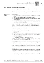
Diagnostic options for CAN communication
Bus Diagnostics
9.4
Diagnostic options for CAN communication
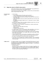
In the event of problems in the communication of MOVIDRIVE
®
using the CAN
interfaces, first check all the parameters of this interface.
If parameters P100 and P101 are set to "SBus1/SBus2", you can monitor the
transmitted setpoints and actual values using parameters P094 - P099.
Possible causes
of error
• Incorrect wiring:
– Are the CAN interfaces of all units properly connected (CAN high, CAN low, CAN
Gnd)?
– Is the ground potential of the units connected with one another?
– Is a proper cable used and has its shield been connected on both ends over a
large surface area?
– Is the bus designed as linear bus structure (without stub lines, not a tree or star
structure)? Does the total cable length match the set baud rate?
– An 120 ohm terminating resistor must be connected each at the start and the end,
or must be activated using DIP switches.
• Is the baud rate and profile setting (CANopen, MOVILINK
®
) the same for all units?
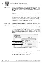
In the CANopen profile, you can check the NMT status and the PDO parameteriza-
tion with the diagnostic tool "CANopen Configuration" in MOVITOOLS
®
Motion-
Studio.
• A certain CAN identifier must only be sent by one station on the CAN. Transmit
telegrams are defined by the following functions:
– Master/slave function
– IPOSplus
®
program (SCOM and MOVILINK
®
commands)
– Engineering PCs
– Controllers
• Depending on the CAN interface, an identifier may be defined only once in a unit as
identifier for a transmit or receive telegram. The assignmentof identifiers results from:
– the profile with its predefined identifiers
– synchronization identifiers
– an IPOS
plus®
program (SCOM and MOVILINK
®
commands)
• If SCOM objects that were defined in an IPOS
plus®
program are not sent, check
whether transmission was activated with SCOMSTAT.
• If manual operation (or the control function in the fieldbus monitor) is still active, then
setpoint transmission via CAN is blocked and another process data assignment
might be active.
• Has timeout monitoring been set correctly, and are cyclic data sent?
• If you receive an error message when accessing a parameter, check the operating
status of the unit or whether the parameter lock is active. Other causes are indicated
in the return codes.
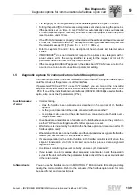
• Bus utilization
A CAN telegram with 8 bytes of useful data has a maximum length of 130 bits and is
transmitted at 500 kBaud in 260
μ
s. This means a maximum of 3 CAN telegrams can
be transmitted per millisecond resulting in a maximum of 7 CAN telegrams at
1 MBaud.
Calculate a reserve of 25% (at least 1 telegram per monitoring interval) for resending
telegrams that might have been damaged by EMC.
Summary of Contents for MOVIDRIVE MDX60B
Page 2: ...SEW EURODRIVE Driving the world...
Page 142: ......
Page 143: ...SEW EURODRIVE Driving the world...

