Manual – MOVIDRIVE® MDX60B/61B Communication and Fieldbus Unit Profile
35
5
Connecting and installing CAN
CAN Interfaces of MOVIDRIVE® B
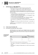
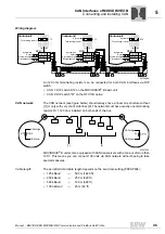
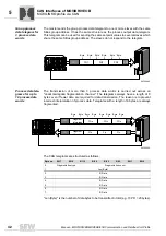
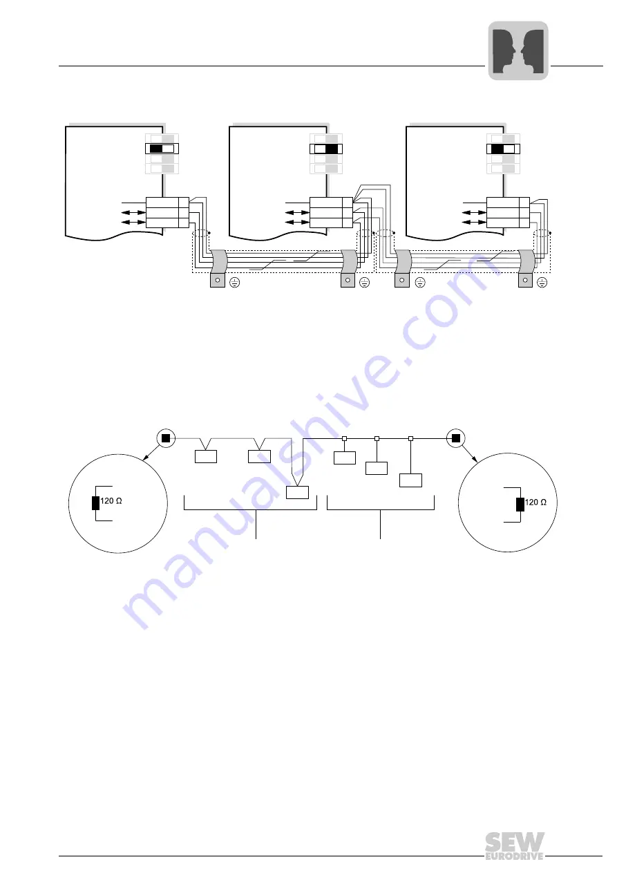
Wiring diagram
An 120 ohm terminating resistor can be connected for both CAN interfaces via DIP
switch.
• CAN 1: DIP switch S12 on the MOVIDRIVE
®
B basic unit
• CAN 2: DIP switch "R" on the DFC11B option
CAN network
The CAN network (see figure below) should always have a linear bus structure without
[1] (or only with very short) stub lines [2]. The network must have exactly one terminating
resistor R
T
= 120 ohm installed on both ends of the bus.
MOVIDRIVE
®
B units come equipped with CAN transceivers with a fan-out of more than
100:1. This means you can connect 100 units via CAN network without having to take
special measures.
Cable length
The permitted total cable length depends on the baud rate setting (P884/P894):
• 125 kBaud
→
500 m (1640 ft)
• 250 kBaud
→
250 m (820 ft)
• 500 kBaud
→
100 m (328 ft)
• 1000 kBaud
→
25 m (82 ft)
64769AEN
X12:
DGND
S
C11
S
C12
1
2
3
S
11
S
1
3
S
14
ON OFF
X12:
DGND
S
C11
S
C12
1
2
3
S
11
S
1
3
S
14
ON OFF
X12:
DGND
S
C11
S
C12
1
2
3
S
11
S
1
3
S
14
S
12
ON OFF
Control unit
Control unit
Control unit
S
y
s
tem
bus
Reference
S
y
s
tem
bus
Reference
S
y
s
tem
bus
Reference
S
y
s
tem
bus
High
S
y
s
tem
bus
High
S
y
s
tem
bus
High
S
y
s
tem
bus
Low
S
y
s
tem
bus
Low
S
y
s
tem
bus
Low
S
y
s
tem
bus
Termin
a
ting re
s
i
s
tor
S
12
S
y
s
tem
bus
Termin
a
ting
re
s
i
s
tor
S
12
Termin
a
ting re
s
i
s
tor
64357AXX
[1]
[2]
CAN-High
CAN-Low
RT
CAN-High
CAN-Low
RT
Summary of Contents for MOVIDRIVE MDX60B
Page 2: ...SEW EURODRIVE Driving the world...
Page 142: ......
Page 143: ...SEW EURODRIVE Driving the world...


