background image

Manual – MOVIDRIVE® MDX60B/61B Communication and Fieldbus Unit Profile 

85

7

Process data description

SEW Unit Profile

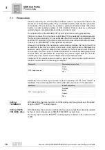
Scaling of 
process data

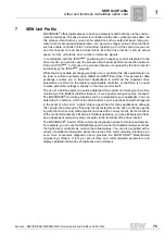
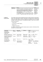
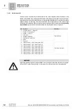
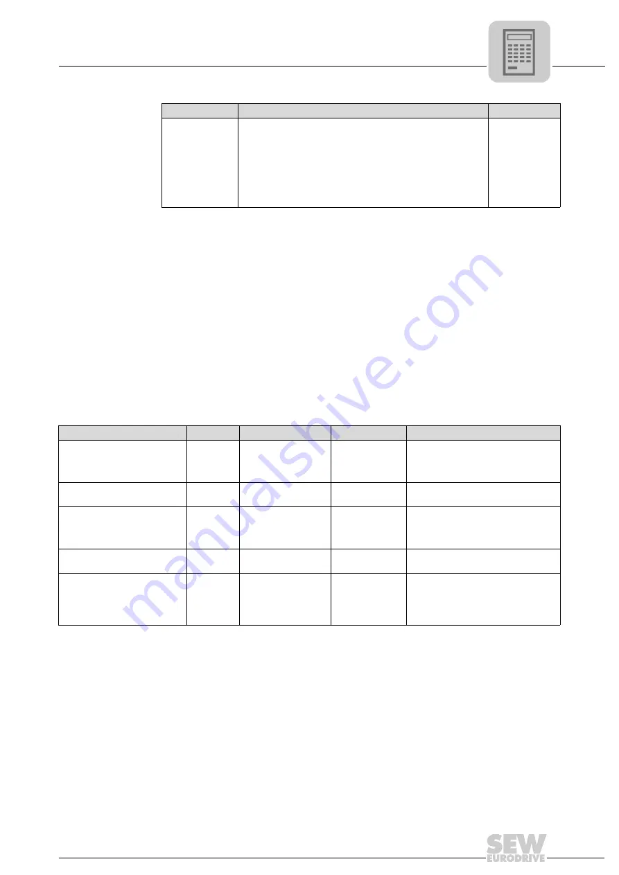
The process data are always transmitted as fixed-point values to make for simple calcu-
lation in the ongoing system process. Parameters with identical units of measurement
receive the same scaling so that the higher-level automation device can directly
compare the set and actual values in the application program. There are the four differ-
ent process data types:
• Speed in rpm
• Current in % I

N

 (rated current)

• Ramp  in  ms
• Position in increments.
The different versions of the control or status word are coded as bit field and will be
described in a separate chapter.

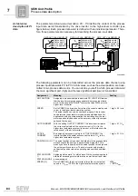
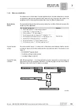
IPOS PI-DATA

Set to 

IPOS PI

 (IPOS Process Input Data), an individual actual 

value can be transmitted from the IPOS

plus®

 program to the 

higher-level controller via process input data. This setting allows 
for exchanging up to 48 individually coded bits between the 
IPOS

plus®

 program and the higher-level controller using the 

process data channel.
You can directly write process input data in IPOS

plus®

 using the 

command 

SetSys PI-Data

. For more detailed information, refer to 

the IPOS

plus®

 positioning and sequency control system manual. 

Three words with 
individually 
coded 16 bits 
each can be 
exchanged 
between the 
higher-level 
controller and 
IPOS

plus®

.

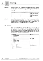
Assignment

Meaning

Scaling

Process data

Type

Resolution

Reference

Range

Speed setpoint / 
Actual speed value / 
Speed limiting slip 
compensation

Integer 16

1 digit = 0.2 rpm

-6553.6 ... 0 ... +6553.4 rpm
8000

hex

 ... 0 ... 7FFF

hex

Relative speed setpoint [%] /
Relative actual speed value [%]

Integer 16

1 digit = 0.0061%
(4000

hex

 = 100%)

Maximum speed 
of the inverter

- 200% ... 0 ... + 200 % - 0.0061%
8000

hex

...0 ... 7FFF

hex

Apparent current actual value /
Actual active current value /
Current setpoint
Current limitation

Integer 16

1 digit = 0.1 % I

N

Rated current of 
the drive inverter

-3276.8% .... 0 ..... +3276.7%
8000

hex

.... 0 ..... 7FFF

hex

Process ramp up / 
Process ramp down

Unsigned 
16

1 digit = 1 ms

delta-f = 100 Hz

0 ms ... 65535 ms
0000hex ... FFFF

hex

Actual position value /
Position setpoint

Integer 32

1 motor revolution = 
4096 increments, i.e.
1 digit = 360°/4096

-188.743.680° .... 0 ..... +188.743.679°
-524 288 .... 0 .... +524287 motor revo-
lutions
8000 0000

hex

 ... 0 ... 7FFF FFFF

hex


high    low 

high   low

Summary of Contents for MOVIDRIVE MDX60B

Page 1: ...Drive Technology Drive Automation System Integration Services MOVIDRIVE MDX60B 61B Communication and Fieldbus Unit Profile Manual Edition 04 2009 11264926 EN...

Page 2: ...SEW EURODRIVE Driving the world...

Page 3: ...1 Transmission method 18 4 3 2 Telegrams 21 4 3 3 Addressing and transmission method 23 4 3 4 Structure and length of user data 26 4 4 Other unit functions via RS485 interfaces 29 4 4 1 Using RS485 in...

Page 4: ...on control 74 7 SEW Unit Profile 75 7 1 Process data 76 7 2 Process data configuration 78 7 3 Process data description 79 7 4 Sequence control 87 7 4 1 Definition of the control word 87 7 4 2 Linking...

Page 5: ...ters for SBus 128 8 6 Communication via Ethernet fieldbus or SBUSplus 129 8 6 1 Connecting the unit with the PC via Ethernet 129 8 7 Executing functions with the units 129 8 7 1 Parameterizing units i...

Page 6: ...y notes The safety notes in this documentation are structured as follows Pictogram SIGNAL WORD Type and source of danger Possible consequence s if disregarded Measure s to prevent the danger Pictogram...

Page 7: ...persons who work independently on the unit You must also ensure that the documentation is legible 1 4 Exclusion of liability You must observe this documentation and the documentation of the connected...

Page 8: ...ere is a danger of invisible external as far as the inverter is concerned modifications to the parameters which give rise to changes in the unit behavior This may result in unexpected not uncontrolled...

Page 9: ...the communication interfaces and how programmable logic controllers PLC can control MOVIDRIVE B via the communication interfaces 3 2 Additional documentation For simple connection of MOVIDRIVE B to f...

Page 10: ...12 X13 0 1 2 2 2 4 5 6 2 2 2 2 0 1 2 3 nc ADDRESS X30 1 2 3 4 DGND SC11 SC12 1 2 3 System bus reference System bus High System bus Low DI DI 1 DI 2 DI 3 DI 4 DI 5 DCOM VO24 1 2 3 4 5 6 7 8 DGND ST11 S...

Page 11: ...ample PROFIBUS DFP21B DeviceNet DFD11B etc for direct connection to the relevant fieldbus system for exchanging process and parameter data Serial interfaces CAN interfaces Fieldbus Terminal socket Soc...

Page 12: ...ams received via a serial interface of MOVIDRIVE B are not passed on via the other serial interface 4 1 Connecting and installing RS485 interfaces 4 1 1 Connection using socket XT The XT socket serial...

Page 13: ...interface is designed as a 9 pole sub D socket EIA standard A Sub D9 extension cable 1 1 connection is supplied for connection to the PC USB11A interface adapter RS485 signals 1 to USB signals 2 You...

Page 14: ...ng resistors are integrated in all SEW components Cable length Maximum cable length 3 m 5 m for shielded cables Baud rate The baud rate for RS485 communication is set using DIP switch S13 on the front...

Page 15: ...cation Use a 4 core twisted pair and shielded copper cable data transmission cable with braided copper shield The cable must meet the following specifications Cable cross section 0 25 0 75 mm2 AWG 23...

Page 16: ...g close to each other using the shortest possible route Avoid using plug connectors to extend bus cables Route the bus cables closely along existing grounding surfaces TIPS When interconnecting the un...

Page 17: ...in serial communication with several inverters we recommend that you do not use address 0 811 RS485 group address 100 199 P811 allows for grouping several MOVIDRIVE B units in one group for communicat...

Page 18: ...ion rate and transmission mechanisms The transmission rate is 9600 baud or 57 6 kBaud via XT only The communications link is monitored by the master and the inverter itself The master monitors the res...

Page 19: ...7 segment display and the enable is ineffective Only when the first tele gram is received enable will take effect and the drive is set in motion If the inverter is controlled via RS485 interface P100...

Page 20: ...RS485 timeout slave Elapsed response time master The inverter does not respond to incorrectly received request telegrams These reception errors have to be evaluated in the master to ensure correct da...

Page 21: ...ng cyclic data exchange the inverter monitors data communication and triggers a timeout response if it has not received another request telegram from the master within a specified time MOVILINK allows...

Page 22: ...e response telegram which the inverter slave sends as response to a request from the master Each response telegram begins with a start pause followed by a start delimiter To clearly distinguish reques...

Page 23: ...an Single addressing Every inverter can be directly addressed using addresses 0 99 The inverter responds to every request telegram from the master with a response telegram ADR Meaning 0 99 Single addr...

Page 24: ...verter can be addressed using universal address 254 independent of the set single address The advantage of this variant is that point to point connections can be established without having to know the...

Page 25: ...is addressing method is mainly used to transmit setpoints The master can send broadcast telegrams at a minimum interval of every 25 ms Consequently an idle time of at least 25 ms is mandatory between...

Page 26: ...egram length depends on the PDU type used and is calculated as follows Telegram length PDU length 4 Transmission methods The following tables show the PDU types for ACYCLIC and CYCLIC transmission met...

Page 27: ...ing the parity bit is even numbered Block parity provides for additional reliability and means that a block check character BCC Block Check Character is added to the telegram Each bit of the block che...

Page 28: ...character is created from the received characters SD1 PD3low according to the pattern described above The telegram has been correctly transmitted if the calculated and received block check characters...

Page 29: ...oint source Master SBus or P100 Setpoint source Master RS485 must be set on the slave The process output data PO1 PO3 P870 P871 P872 are automatically set by the firmware A programmable terminal funct...

Page 30: ...ation via RS485 interface set P811 RS485 Group address to a value greater than 100 If you have made the setting in parameter P750 slave setpoint that slave setpoints are used via RS485 then MOVIDRIVE...

Page 31: ...ERVO CFC SERVO IPOS CFC SERVO SYNC MASTER SBus1 MASTER RS485 VFC n CONTROL VFC n CTRL GROUP VFC n CTRL HOIST CFC SERVO Speed synchronization Master controlled Slave controlled Drives do not have a rig...

Page 32: ...101 Control signal source e g TERMINALS Not in effect P700 Operating mode 1 VFC n CONTROL VFC 1 P750 Slave setpoint SPEED SBus MASTER SLAVE OFF P751 Scaling slave setpoint Not in effect 1 then 1 1 P81...

Page 33: ...ose set the bus type to the value 1 for accessing the XT socket master functionality and to value 2 for access via X13 4 4 3 Using RS485 interfaces for manual operation Manual operation of MOVIDRIVE B...

Page 34: ...ly synchronizing several MOVIDRIVE B units ISYNC For connection to an engineering PC via PC CAN interface or SEW fieldbus gate way For sending and receiving user defined data CAN layer 2 communication...

Page 35: ...nsceivers with a fan out of more than 100 1 This means you can connect 100 units via CAN network without having to take special measures Cable length The permitted total cable length depends on the ba...

Page 36: ...id using plug connectors to extend bus cables Route the bus cables closely along existing grounding surfaces TIPS Do not operate both CAN interfaces with 1000 kBaud to limit the interrupt load for MOV...

Page 37: ...ce 120 at 1 MHz Capacitance per unit length 40 pF m at 1 kHz Suitable cables are e g CAN bus or DeviceNet cables Shield contact Connect the shield on both sides to the electronics shield clamp of MOVI...

Page 38: ...the setpoints 881 882 SBus address 1 2 0 63 Setting of the SBus address used for exchanging parameter and process data 882 892 SBus group address 1 2 0 63 Setting for the SBus group address used for r...

Page 39: ...s of identifiers ID or COB ID Communication Object Identifier Therefore the identifier of a CAN telegram is generated from the telegram type and the address set using parameters P881 P891 SBus address...

Page 40: ...tifiers of the process or parameter data telegrams Identifier Telegram type 8 SBus address 3 Process output data telegram PO 8 SBus address 4 Process input data telegram PI 8 SBus address 5 Synchroniz...

Page 41: ...at sent at certain points of time during the fixed time base of 5 milli seconds A distinction is made between synchronous and asynchronous process data The synchronous process data are sent within th...

Page 42: ...data words is carried out across an unacknowlegded fragmentation channel The telegrams always have a length of 8 bytes even if fewer data are required for data transmission The reason is to prevent in...

Page 43: ...The management byte specifies the service to be performed The index specifies the parameter for which the service is to be performed The 4 data bytes contain the number value to be read or written se...

Page 44: ...telegram 5 3 2 Parameter setting via CAN SBus MOVILINK With the SBus MOVIDRIVE inverters support the MOVILINK parameter channel and MOVILINK parameter channel SYNC In conjunction with the CAN bus it...

Page 45: ...at www sew eurodrive de under Documentation Software The CANopen profile provides the following COB ID Communication Object Identifier and functions 01028BEN 01110010 01110010 CAN Control Master Drive...

Page 46: ...t NMT Baud rate and CANopen slave address Parameters P884 P894 are used to set the CAN baud rate The baud rate can only be set to 1 Mbaud when the baud rate of the other Sbus is 125 kBaud The CANopen...

Page 47: ...he address set in parameter P886 896 The value 0 is permitted for the node ID In this case all CANopen devices will be addressed NMT services are not acknowledged by the slave MOVIDRIVE B supports the...

Page 48: ...PO9 PO10 TX PDO1 with PI1 PI2 PI3 TX PDO2 with PI4 PI5 PI6 TX PDO3 with PI7 PI8 PI9 PI10 All RX PDOs and TX PDOs operate in the synchronous transmission mode TX PDO2 and TX PDO3 are disabled and can b...

Page 49: ...mission mode 254 A TX PDO2 is sent directly after a valid RX PDO2 has been received valid means that the length is not too long or too short Event controlled and asynchronous value 255 This TX PDO is...

Page 50: ...time This inhibit time is a lock out time for TX PDOs The inhibit time for a TX PDO begins once this object has been sent This object cannot be sent to the CANopen bus again until the inhibit time ha...

Page 51: ...PDO The value to be written is calculated from 65535 index 256 subindex 16 The result for RX PDOs mapping entries is 20210x10hex with x being a value between 1 and Ahex and designating the number of t...

Page 52: ...f the SYNC object as 080hex The COB ID should be changed in the pre operational unit state Although it can also be changed in the operational status the CAN controller is temporarily sepa rated from t...

Page 53: ...bles If MOVIDRIVE B is not to send an EMCY object you can deactivate it by setting bit 31 The COB ID is addressed as unsigned long via index 1014hex subindex 0 In initializing status the MOVIDRIVE B d...

Page 54: ...product of life time factor guard time is 0 the node guarding function is deactivated and the heartbeat mechanism can be used see section Hearbeat Heartbeat MOVIDRIVE B is a heartbeat producer The tim...

Page 55: ...3 write 4 bytes command 60 successfully written response 4F 1 byte read response 4B 2 bytes read response 43 4 bytes read response 80 error while executing service response In the 4 byte data range of...

Page 56: ...2116 ramp up CW is to be written to the volatile memory with the value 0x4000000 write volatile service 0x33 Before the service is executed the MOVILINK service data Index 0x2067 must be set to the va...

Page 57: ...e time factor rw UNSIGNED8 NO 0 100E 0 COB ID lifetime rw UNSIGNED32 NO 0 100F 0 no of SDO ro UNSIGNED32 NO 1 1014 0 COB ID EMCY message rw UNSIGNED32 NO 80hex slave ID 1015 0 inhibit time EMCY ms rw...

Page 58: ...r no of entries ro UNSIGNED32 NO 3 1800 1 COB ID rw UNSIGNED32 NO 40000180hex slave ID 1800 2 transmission type rw UNSIGNED8 NO 1 1800 3 inhibit time 100 s rw UNSIGNED16 NO 0 1801 0 TX PDO2 parameter...

Page 59: ...2020 4 PO 4 rrw SIGNED16 YES 0 2020 5 PO 5 rrw SIGNED16 YES 0 2020 6 PO 6 rrw SIGNED16 YES 0 2020 7 PO 7 rrw SIGNED16 YES 0 2020 8 PO 8 rrw SIGNED16 YES 0 2020 9 PO 9 rrw SIGNED16 YES 0 2020 10 PO 10...

Page 60: ...ss P882 must be set for master and slaves The valid address range is 0 63 Permitted baud rates for master slave operation are 500 kBaud and 1000 kBaud P884 Make sure that the baud rate is the same for...

Page 61: ...data and SETSYS PI data Depending on the chosen profile P880 890 the data are read or written in CANopen format low byte first or in MOVILINK format high byte first access process and parameter data o...

Page 62: ...th an object oriented approach The stations send objects and those stations which want to process these objects receive them The variable telegrams are created independent of the profile set with the...

Page 63: ...every 5 ms It is created in IPOSplus using the _SBusCommDef command C The synchronization ID P817 or P885 895 with MOVIDRIVE B must be different from the object number of the synchronization message...

Page 64: ...the master position of this master to its slaves The object number should be as small as possible see 4 D but greater than the object number chosen for 1 A 4 The following requirements must be fulfil...

Page 65: ...s possible if the baud rate is set to 250 or 125 kBaud Individual cases where these limits are exceeded have to be checked thoroughly C Ensure that the entire calculated bus utilization does not excee...

Page 66: ...s baud rate 1 2 All stations on the SBus must be set to the same baud rate Baud rate maximum cable length and telegrams time depend on one another P885 P895 See points 1B 2A and 4A The time slice can...

Page 67: ...for PROFINET IO DFE33B for EtherNet IP and Modbus TCP DFC11B for CAN 2 SBus 2 A manual is available for each fieldbus option mentioned aboved except for DFC11B This manual provides detailed informati...

Page 68: ...ing a fieldbus option card in MOVIDRIVE MDX61B TIPS Only SEW EURODRIVE personnel may install or remove option cards for MOVIDRIVE MDX61B size 0 Users may only install or remove option cards for MOVIDR...

Page 69: ...measures to protect the option card from electrostatic charge use discharge strap conductive shoes etc before touching it Before installing the option card remove the keypad and the front cover MOVIDR...

Page 70: ...m the slot do not twist 2 Remove the 2 retaining screws from the black cover plate on the card retaining bracket Remove the black cover plate 3 Position the option card onto the retaining bracket so t...

Page 71: ...P is activated using P785 the value specified by the DHCP server will be displayed 781 Subnetwork mask 000 000 000 000 255 255 255 0 255 255 255 255 Factory setting at delivery is a class C network Th...

Page 72: ...on PI1 Actual value description PI2 Actual value description PI3 Enable PO data Factory set to STATUS WORD 1 SPEED NO FUNCTION ON The content of process input data words PI1 PI2 PI3 is defined 887 Syn...

Page 73: ...data and SETSYS PI data Set the bus type to 3 for this purpose 6 4 2 Engineering via fieldbus In addition to accessing process and parameter data by the controller some fieldbus options e g DFP21B DF...

Page 74: ...the Ethernet network you can have a read access to diagnostic parameters for example in the Internet Explorer by entering the IP address of MOVIDRIVE Diagnostics via web server is described in manuals...

Page 75: ...eters are stored in the master programmable controller so that there is no need to make parameter settings manually on the drive inverter itself The use of a fieldbus system requires additional drive...

Page 76: ...rce and setpoint source Distinguishing between control signal and setpoint source allows for the most various combinations For example the drive can be controlled via fieldbus and uses the analog setp...

Page 77: ...wire or program the terminals in such a way that the inverter is enabled via the binary inputs DI00 Controller inhibit DI01 no function DI02 no function DI03 no function DI04 no function DI04 no func...

Page 78: ...ollowing process data configura tions might take effect Only the number of process data that is 1 PD 10 PD is interesting for process data control of the drive inverter These process data are usually...

Page 79: ...ated again P876 PO data enable ON will the received process output data be processed according to the new actual and set point value descriptions Process data words 4 to 10 can only be read and writte...

Page 80: ...ss output data usu ally a position setpoint as 32 bit value directly to the IPOSplus program in IPOSplus variable 499 SP PO BUS setpoint position bus The position setpoints must be split into two proc...

Page 81: ...this process ramp When transmitting the process ramp via the field bus system ramps t11 t12 t21 and t22 become ineffective 1 digit 1 ms CONTROL WORD 1 CONTROL WORD 2 The assignment of process output d...

Page 82: ...ion via fieldbus If a communication interface is entered as control signal source and if no control word is programmed for the process output data description then the ENABLE control command is specif...

Page 83: ...value description PI3 RS485 FIELDBUS System bus 1 PI 1 PI 2 PI 3 Bus diagnostics 097 PI1 actual value hex 098 PI2 actual value hex 099 PI3 actual value hex 870 setpoint description PO1 871 setpoint de...

Page 84: ...h slip compensation the deviation from the real motor speed solely depends on the accuracy of the slip compen sation set by the user 1 digit 0 2 min OUTP CURRENT With the setting OUTPUT CURRENT the dr...

Page 85: ...r using the process data channel You can directly write process input data in IPOSplus using the command SetSys PI Data For more detailed information refer to the IPOSplus positioning and sequency con...

Page 86: ...e two process output data used for transmitting the position are handled consistently This means that the position setpoint high is always transmitted together with the position setpoint low Process d...

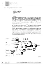
Page 87: ...tivated by the control word The individual control word bits are considered as reserved and must be set to logical 0 by the user Basic control block The less significant part of the control word bits...

Page 88: ...ediately even without the IPOSplus program The binary inputs will generally remain active even if the inverter is controlled via the process data P101 control signal source RS485 FIELDBUS SBus Safety...

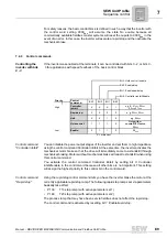
Page 89: ...mechanical braking Motors without mechanical brake will coast to standstill when using this control command You activate the control command Controller inhibit by setting bit 0 Controller inhibit ena...

Page 90: ...ators ramp up for this control command depending on the set parameters and in tegrator set All three bits must be set to Enable 110 bin for the control command Enable Control command Hold control Sett...

Page 91: ...d has no effect on the motor potentiometer function Only the following motor potentiometer integrators will be used P150 T3 Ramp up P151 T4 Ramp down Bit Functionality Assignment 0 Fixed definition Co...

Page 92: ...ionality can be programmed as required Bit Function Definition 0 Controller inhibit 1 Enable 0 Fixed definition 1 Enable 1 Rapid stop 0 2 Enable 1 Stop 0 3 Hold control 4 Integrator switchover 5 Param...

Page 93: ...nals a fault the factory setting is active setup no supply voltage is present Signal PO data enabled With PO data enabled 1 bit 2 signals that the inverter responds to control values and setpoints fro...

Page 94: ...mit switches is indicated in the drive inverter as 1 active 7 4 7 Status word 1 Status word 1 contains the status information in the basic status block and the unit status or the fault number in the h...

Page 95: ...nabled 3 Current ramp generator set 4 Current parameter set 5 Fault warning 6 Limit switch CW active 7 Limit switch CCW active 8 Virtual terminal 1 P630 Binary output DO10 Virtual output terminals 9 V...

Page 96: ...te Depending on the fault bit the unit status is displayed for fault bit 0 or for problems fault bit 1 the error number The fault bit is reset by resetting the fault and the current unit status is dis...

Page 97: ...V operation inverter not ready 1 1 Controller inhibit active 2 2 No enable 3 3 Standstill current 4 4 Enable 5 5 n control speed control 6 6 M control torque control 7 7 Hold control 8 8 Factory setti...

Page 98: ...splay sequence is used e g fault code 100 Following a reset or if the fault code resumes the value 0 the display switches to the operating display The suberror code is displayed in MOVITOOLS as of ver...

Page 99: ...every communica tion interface Timeout interval The timeout interval can be set individually for each communication interface Timeout response The timeout response can be set individually for each co...

Page 100: ...e individual bus systems Parameters for fieldbus timeout Value range Unit Seconds Range 0 01 s to 650 00 s in 10 ms steps Special case 0 or 650 00 Fieldbus timeout disabled Factory setting 0 5 s TIP W...

Page 101: ...systems and is explained in detail below Also refer to the documentation for the fieldbus option card to obtain additional program ming information on using the MOVILINK parameter channel with the var...

Page 102: ...tem manual A special number index is assigned to each parameter This number is used to read or write the parameter Data range bytes 4 7 The data is located in byte 4 to byte 7 of the parameter channel...

Page 103: ...et to 0 bytes 4 to 7 of the response telegram will contain the requested data If the status bit is set to 1 an error code is indicated in the data area bytes 4 to 7 see chapter Incorrect service execu...

Page 104: ...Coding takes place according to the sensor actuator profile of the PROFIBUS user organization PUO The entry FFhex means that no measurement index is specified You can also obtain the measurement index...

Page 105: ...handshake bit the inverter has executed the service Byte 4 Byte 5 Byte 6 Byte 7 MSB data Data Data LSB data Next available index Access attributes Byte 6 Byte 7 Bit Bit Meaning 0 1 Parameter allows w...

Page 106: ...50170 The error class is generated by the communication software of the fieldbus interface if there is an error in communication This statement does not apply to Error class 8 Oth er error Return cod...

Page 107: ...Additional code Error class High Low Description 0x05 00 0x00 Unknown error 0x01 Illegal Service 0x02 No Response 0x03 Different Address 0x04 Different Type 0x05 Different Index 0x06 Different Servic...

Page 108: ...ue too small 0x17 Required Hardware does not exist 0x18 Internal Error 0x19 Access only via RS485 via X13 0x1A Access only via RS485 via XT 0x1B Parameter protected 0x1C Controller inhibit required 0x...

Page 109: ...When using acyclic PDU types every inverter processes every request telegram and in this way always executes the parameter channel The parameters are set as follows 1 Enter the index of the parameter...

Page 110: ...anagement 7 6 5 4 3 2 1 0 0 0 1 1 1 0 0 0 1 Service identifier 0001 Read Data length 11 4 bytes Handshake bit Must be changed with every new job Status bit 0 No error while executing service 1 Error w...

Page 111: ...xecutes the parameter channel The parameters are set as follows 1 Enter the index of the parameter to be written in byte 2 index high and byte 3 index low 2 Enter the data to be written in bytes 4 7 3...

Page 112: ...rvice but continues to respond to all telegrams with handshake bit 0 The executed service is acknowledged with a change of the handshake bit in the response message of the drive inverter The master no...

Page 113: ...n is that the control signal source and setpoint source are reset to their default values Parameter lock The parameter lock is activated by setting P803 Parameter lock Yes It protects all adjustable p...

Page 114: ...annels using their communication options You can operate up to four communication channels at the same time MOVITOOLS MotionStudio supports the following communication channels Serial RS485 via interf...

Page 115: ...e and storage location 8 2 2 Establishing communication and scanning the network Proceed as follows to establish a communication with MOVITOOLS MotionStudio and scan your network 1 Set up a communicat...

Page 116: ...cation mode you have selected The following figure illustrates the two types of tools 64335AXX Tools Description Offline tools Changes made using offline tools affect ONLY the RAM 2 Save your project...

Page 117: ...to open the context menu and display the tools for configuring the unit TIP The online communication mode is NOT a response message which informs you that you are currently connected to the unit or t...

Page 118: ...1A interface adapter How to connect the interface adapter to MOVIDRIVE B is described in chapter 4 Serial Interfaces of MOVIDRIVE B 8 4 2 Taking the USB11A interface adapter into operation Overview Th...

Page 119: ...nd MOVIDRIVE B proceed as follows 1 Connect the USB11A interface adapter 2 with the two connection cables provided 2 Plug the RJ10 connector of the first connection cable into the XT socket 3 of MOVID...

Page 120: ...e wizard 4 Click on Browse and go to the MOVITOOLS MotionStudio installation folder 5 Enter the following path Program Files SEW MotionStudio Driver FTDI_V2 6 Click the Next button to install the driv...

Page 121: ...the units you want to configure You can establish one for example using the USB11A interface adapter Proceed as follows to configure serial communication 1 Click on Configure communication plugs 1 in...

Page 122: ...ress the Edit button 3 on the right side of the Configure communication plugs window This will display the settings for the Serial communication type 4 If necessary change the preset communication par...

Page 123: ...he network via the com munication channel Possible values 9 6 kBit s 57 6 kBit s AUTO default setting Find the correct value for the connected unit in the documen tation If you set AUTO the units are...

Page 124: ...des a prefabricated connection cable on the unit with terminating resistor There fore only this PC CAN interface is described in the following chapter 8 5 2 Taking the USB CAN interface into operation...

Page 125: ...ect the 9 pin D sub connector of the USB CAN interface with the prefabricated connection cable Make sure that the cable end with the terminating resistor leads to the USB CAN interface 2 Connect the s...

Page 126: ...AN interface for this purpose Proceed as follows to configure an SBus communication 1 Click on Configure communication plugs 1 in the toolbar Doing so will open the Configure communication plugs windo...

Page 127: ...s the Edit button 3 on the right side of the Configure communication plugs window This will display the settings for the SBus communication type 4 It might be necessary to change the preset communicat...

Page 128: ...values permitted total cable length 125 kBaud 500 m 250 kBaud 250 m 500 kBaud 100 m default 1 MBaud 25 m All connected units must support the same baud rate Communication parameters Description Note...

Page 129: ...arranged in folders You can manage the unit parameters using the context menu or toolbar The following chapter describes how to read or change unit parameters 8 7 2 Reading changing unit parameters T...

Page 130: ...nits online To startup units online proceed as follows 1 Switch to the network view 2 Click the Switch to online mode button 1 3 Select the unit you want to startup 4 Open the context menu and select...

Page 131: ...and actual values which are exchanged between master controller and MOVIDRIVE inverter so you can monitor and analyze them You obtain all the information of the three process data channels such as des...

Page 132: ...s The figure below shows all communication parameters of the MOVIDRIVE inverter which can also be used for detailed diagnostic purposes 9 1 Checking the parameter setting The parameters of the MOVIDRI...

Page 133: ...093 Fieldbus address System bus 1 2 881 891 SBus address 1 2 880 890 CAN profile 882 892 SBus group address 1 2 883 893 SBus timeout interval 1 2 884 894 SBus baud rate 1 2 885 895 SBus synchronizati...

Page 134: ...ual value hex For this purpose MOVITOOLS MotionStudio reads the process data sent from and received by the drive inverter Not all process data cycles are displayed due to different transmission speeds...

Page 135: ...rs and operator panels For RS485 masters that were not developed by SEW EURODRIVE ensure correct telegram structure pause before the start delimiter and character delay Also make sure that RS485 teleg...

Page 136: ...quest Chapt Telegrams section Structure of response telegrams 1 0x02 RS485 address 2 Chapter Addressing and transmission method 2 0x86 User data type Acyclic 8 bytes Chapter Structure and length of us...

Page 137: ...ntifier must only be sent by one station on the CAN Transmit telegrams are defined by the following functions Master slave function IPOSplus program SCOM and MOVILINK commands Engineering PCs Controll...

Page 138: ...grams shortcuts are created under Start Programs SEW sCAN and PCAN Tools when installing MOVITOOLS MotionStudio Example Process data exchange using PCAN View For exchanging process data between PC and...

Page 139: ...set to Fieldbus you can monitor the transmitted setpoints and actual values as well a some fieldbus settings using parameters P094 P099 If one of the industrial Ethernet interfaces DFE32B DFE33B is u...

Page 140: ...trol commands Controller inhibit 89 Enable 90 Hold control 90 Rapid stop 89 Stop 90 Control signal source RS 485 76 TERMINALS 76 control signal source FIELDBUS 76 SBus 76 Control word definition 87 Ba...

Page 141: ...on 87 Safety relevant control commands 88 Status word 1 status word 1 94 Status word 2 status word 2 95 Status word 3 status word 3 96 Status word definition 93 Serial 12 118 123 Serial interfaces Soc...

Page 142: ......

Page 143: ...SEW EURODRIVE Driving the world...

Page 144: ...reduces the cost and complexity of daily operations With a global presence that offers responsive and reliable solutions Anywhere With innovative technology that solves tomorrow s problems today With...

Reviews: