10
Manual – MOVIDRIVE® MDX61B Synchronous Operation Board DRS11B
3
Synchronous operation with cable-break monitoring of encoder connection
Project planning
•
If the master is an external incremental encoder, use incremental encoders with as
high a resolution as possible. However, the maximum input frequency of 200 kHz
must not be exceeded.
•
Parameter
P350 Change direction of rotation 1
:
When synchronous operation control is activated, P350 must be set to NO. If the
master and slave are to operate in opposite directions, the connection sequence of
the A/A and B/B tracks at the slave input (DRS11B:X42) must be swapped over in
each pair.
•
The 24 V DC connection at DRS11B:X44 is mandatory in the following cases:
– The encoder voltage supply is connected via option DRS11B
– The binary outputs (X40:9, X40:10) or DRS11B are used.
– X40:8 is used as voltage output
•
Encoder monitoring at X41/X42 is only possible with TTL encoders.
3.3
Synchronous operation with cable-break monitoring of encoder connection
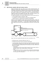
For fault-free synchronous operation between master and slave, cable-break monitoring
is required for the connection between master DEH11B/DER11B:X14 (incremental
encoder simulation) and slave RS11B:X42. The following functions are available:
•
"MOTOR STANDSTILL" and "DRS MAST. STOPPED"
•
"/EXT. FAULT" and "/FAULT"
The only time when encoder pulses are not transferred to the slave is when the master
is at a standstill. Therefore, this status is communicated to the slave via a binary
connection. If the master does not report a standstill and the slave does not count any
encoder pulses, there is either a cable break or the master encoder is defect. As a result,
the slave switches off and communicates its status to the master via an additional
connection.
Required
connections
•
Program one binary output of the master to the function "MOTOR STANDSTILL."
Connect this output to a binary input on the slave, that is programmed to the function
"DRS MAST. STOPPED."
•
Program one binary input of the master to the function "/EXT. FAULT." Connect this
input to a binary output on the slave, that is programmed to the function "FAULT."
Additional encoder monitoring can be activated with P516 or P519 (
→
Sec. 6).


