16
Manual – MOVIDRIVE® MDX61B Synchronous Operation Board DRS11B
4
Installation notes
Assembly and installation instructions
4.3
Installation notes
•
Maximum permitted cable lengths:
– Between master inverter and slave inverters: 10 m
– Between the inverters and the encoders: 100 m
•
Only use shielded encoder cables with twisted pair conductors (A and A, B and B, C
and C) to connect:
– Motor encoders and synchronous encoders
– Incremental encoder simulations
– Encoder input of master encoder
•
If necessary, connect a DC 24 V voltage supply to X44. This is used to supply
encoders connected to X41 and X42, the binary inputs X40:9 and X40:10 and volt-
age output X40:8. Note that the total current load at X41 and X42 must be
≤
650 mA.
•
Note the following when connecting incremental encoders to an external supply:
– Connect the reference potential of the encoder to the connection X10:2 DGND or
X10:10 DGND on the MOVIDRIVE
®
basic unit.
•
Enable command on slave inverter for synchronous operation (with standard default
assignment of DI01, DI02 and DI03):
– DI00 (X13:1)= "1" (/Controller inhibit), DI03 (X13:4) = "1" (Enable) and
– DI01 (X13:2) = "1" (CW) or DI02 (X13:3) = "1" (CCW)
Keep in mind: During synchronous operation, the direction of rotation of the slave is
determined by the direction of rotation data of the setpoint pulses passing from the
master to the slave.
•
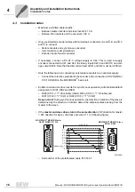
If the master and slave drives turn in the same direction (CW direction for master
= CW direction for slave), the tracks are wired 1:1 (
→
following figure).
– Part number of the prefabricated cable: 818 166 7
56525AEN
1
5
6
9
1
8
9
15
MOVIDRIVE
®
MDX61B Master
DEH11B/DER11B X14
MOVIDRIVE
®
MDX61B Slave
DRS11B X42
max. 10m
A
B
C
A
B
C
A
B
C
^
A
B
C
1
9
2
10
3
11
7
1
6
2
7
3
8
4
^
^
8
5
Changeover


