18
Manual – MOVIDRIVE® MDX61B Synchronous Operation Board DRS11B
4
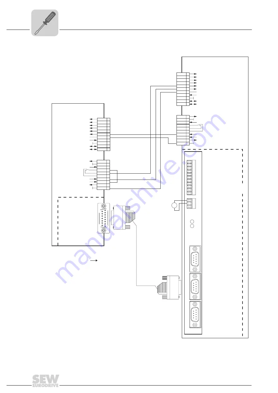
MOVIDRIVE® MDX61B master – MOVIDRIVE® MDX61B slave connection
Assembly and installation instructions
4.4
MOVIDRIVE
®
MDX61B master – MOVIDRIVE
®
MDX61B slave connection
56544CEN
DRS11B
0
4
X
4
4
X
1
4
X
2
4
X
3
4
X
Sync
OFF
1
5
6
9
5
1
9
6
5
1
9
6
1
2
3
1
2
3
4
5
6
7
8
9
10
11
EING0; Free-runnng
EING1; Offset 1
EING2; Offset 2
EING3; Offset 3
EING4; IPOS
plus
variable H477.0
EING5; IPOS
plus
variable H477.1
DCOM; Ref. X40:Eing0...Eing5
VO24; 100mA
AUSG0; 50mA; IPOS
plus
variable H476.0
AUSG1; 50mA; IPOS
plus
variable H476.1
DGND
GND
DC 24 V
GND
Incremental encoder input
Synchronous encoder
Incremental encoder input
Master encoder
Incremental encoder output
DI00
1
/Controller inhibit
/Brake
/Fault*
DI01
CW/stop*
CCW/stop*
2
DI02
3
DI03
Enable/stop*
4
DI04
DRS MASTER STOPPED
5
DI05
DRS SLAVE START
6
DCOM
Reference X13:DI00...DI05
7
VO24
DC+24 V output
8
DGND
Reference potential for binary signals
Reference potential for binary signals
Ref. potential for binary signals
9
ST11
RS485+
RS485-
10
ST12 11
X13:
X10:
X10:
TF1
Input TF-/TH-/KTY+
1
DGND 2
DB00 3
DO01-C
DO02
Relay contact/ready*
Normally open contact relay
Normally closed contact relay
4
DO01-NO
DO01-NC
5
6
7
VO24
DC+24 V output
8
VI24
DC+24 V input
9
DGND 10
DI00
1
/Controller inhibit
DI01
CW/stop*
CCW/stop*
2
DI02
3
DI03
Enable/stop*
4
DI04
n11/n21*
5
DI05
/ext. fault
6
DCOM
Ref. X13:DI00...DI05
7
VO24
DC+24 V
8
DGND
Ref. potential for binary signals
9
ST11
RS-485+
RS-485-
10
ST12 11
X13:
/Brake
Output stage ON
Ref. potential for binary signals
Ref. potential for binary signals
TF1
TF-/TH-/KTY+ input
1
DGND 2
DB00 3
DO01-C
DO02
Motor standstill
Normally closed contact relay
Normally open contact relay
4
DO01-NO
DO01-NC
5
6
7
VO24
DC+24 V output
8
VI24
DC+24 V input
9
DGND 10
MOVIDRIVE
®
MDX61B Master
MOVIDRIVE
®
MDX61B Slave
Cable-break monitoring
[1]
[1] Part numbers of the prefabricated cable
DEH11B/DER11B:X14
- same direction of rotation: 818 166 7
- different direction of rotation 818 167 5
DRS11B:X42
-
+
V
DC 24 V
*
Factory setting
DEH11B / DER11B
X14
simulation
Incremental encoderr-
1
9
8
15

