24
Manual – MOVIDRIVE® MDX61B Synchronous Operation Board DRS11B
5
Examples for the calculation of P221 and P222
Startup
5.6
Examples for the calculation of P221 and P222
Example 1: Chain
conveyor
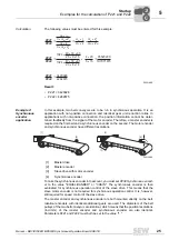
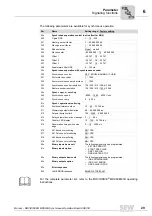
In this example, two chain conveyors are to be run in synchronous operation (
→
follow-
ing figure). It is an application with positive connection and different gear unit reduction
ratios. A synchronous encoder is not required; for applications with positive connection,
the travel information can be calculated from the signal of the motor encoder [1].
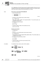
The goal of the following calculation is to determine the ratio of the position resolution
for master and slave. You can obtain the numbers of teeth in the gear pairs from SEW-
EURODRIVE on request.
Data
Master drive: K87 DT100L4 BM ES1 (with motor encoder)
•
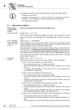
Gear unit reduction ratio:
•
Resolution of the incremental encoder (master and slave drive):
A
M
= 1024 incr./rev.
Incremental encoders supply 1024 pulses/revolution. The encoder pulses are qua-
drupled in the inverter.
•
Position resolution of master [incr./mm]:
(A
M
×
i
M
) / (
Π
×
m
M
×
Z
M
)
Module m
M
= 5
No. of teeth Z
M
= 15
U
M
= m
M
×
Z
M
Slave drive: KA67 DT100LS4 BM ES1 (with motor encoder)
•
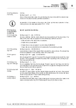
Gear unit reduction ratio:
•
Resolution of the incremental encoder (master and slave drive):
A
S
= 1024 incr./rev.
Incremental encoders supply 1024 pulses/revolution. The encoder pulses are
quadrupled in the inverter.
•
Position resolution of master [incr./mm]:
(A
S
×
i
S
) / (
Π
×
m
S
×
Z
S
)
Module m
S
= 4
No. of teeth Z
S
= 20
U
S
= m
S
×
Z
S
56514AXX
[1]
56587AXX
56588AXX
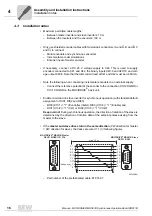
i
M
=
=
40
x
33
x
83
36.52
25
x
8
x
15
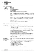
i
S
=
=
47
x
33
x
81
48.77
23
x
8
x
14
0
0
I

