Manual – MOVIDRIVE® MDX61B Synchronous Operation Board DRS11B
27
6
Relationship between parameter values and output speed
Parameter
6
Parameter
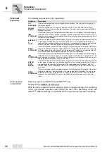
Explanation of
the parameters
The parameter names correspond to those displayed in MOVITOOLS
®
SHELL. The
factory setting is indicated by underline.
Symbol
6.1
Relationship between parameter values and output speed
In the case of adjustable parameters (P224, P225, P226, P227, P510, P511, P512,
P514), you must enter increments which relate to an angle offset (e.g. as a permitted
deviation or offset) between the master and slave drives. They refer to the value that the
inverter calculates on the basis of the encoder pulses. The number of encoder pulses is
multiplied by a factor of 4 in the inverter.
The number of increments that you have to enter for parameters is calculated from the
angular offset of the motor according to the following formula:
Incremental value to be entered = motor revolutions
×
4
×
number of pulses of
incremental encoder
Example
If the fault message "/DRS LAG ERROR" is to be generated for a deviation of 5 motor
revolutions and incremental encoders with a resolution of 1024 increments / revolution
between the master and slave drives are used, enter the following as the increment
value in
P512 Lag error limit
.
Counter value to be entered = 5
×
4
×
1024 = 20480
This value can also be applied to the gear unit output side:
Motor revolutions = Gear unit output revolutions
×
i
gear unit
In addition to the motor speed and the gear unit reduction ratio, the additional gear also
has an effect on the effective output speed at the output machine. In this case, you can
calculate the motor revolutions as follows:
Motor revolutions = Gear unit output revolutions
×
i
gear unit
×
i
add. gear
These parameters can only be changed with INHIBITED inverter status (= output
stage at high resistance).
P6..
P60.
P600


