Manual – MOVIDRIVE® MDX61B Synchronous Operation Board DRS11B
5
2
System description
Introduction
2
Introduction
2.1
System description
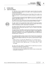
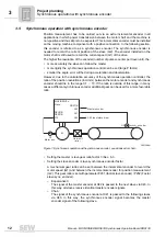
The "DRS11B synchronous operation board" enables a group of motors to be operated
at a synchronous angle in relation to one another or with an adjustable proportional
relationship (electronic gear).
The drive that specifies the position is known as the "master." This can also be an
incremental encoder. The drive that follows the position specification is known as the
"slave."
To be able to function in this way, the master and slave motors must be equipped with
encoders. MOVIDRIVE
®
MDX61B with the "DRS11B synchronous operation board"
option is used as the slave drive.
The "DRS11B synchronous operation board" option must be plugged into the expansion
slot and can only be operated in conjunction with the DEH11B or DER11B option.
The master and slave pulses counted are converted for the output side using parameter
P221/P222 (master and slave gear ratio factor). They are a measure for the pulses
counted per travel unit.
The system determines the difference of the distance information from master and slave
and stores this value in the form of incremental encoder signals in an internal differential
counter. Binary messages are set, e.g. "DRS SLAVE IN POS," "LAG ERROR," etc.
depending on the difference. The counter is evaluated differently for the various operat-
ing modes (P223) (
→
section 6.3).
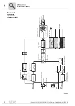
The controller calculates the speed correction value for the slave drive to minimize the
angle differential between the master and slave. To do so, the current angle differential
is multiplied by the parameter
P220 P gain
. The result is a correction value for the slave
speed.
•
Master and slave run synchronously, differential value = 0
→
correction value = 0
•
Slave follows master, differential value > 0
→
correction value > 0, slave accelerates
•
Slave runs ahead of master, differential value < 0
→
correction value < 0, slave
decelerates
The value of the P gain (P220) is a significant factor for determining the movement
characteristics of synchronous operation control.
•
If the P gain is set too high, the system tends to oscillate.
•
If the P gain is set too low, the angle differential cannot be reduced in a transient state
(acceleration or deceleration).
The slave inverter must be equipped with a braking resistor for synchronous operation
of master and slave. The master inverter may also have to be equipped with a braking
resistor for regenerative operation, depending on the application.


