48
Operating Instructions – MOVIFIT® FDC
5
Installation topologies
Electrical Installation
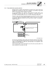
5.4.3
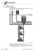
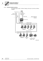
Combined installation topology
The following figure shows a combined topology with single line network and SBus
installation:
5978456843
PLC
24 V
Line
filter
Pre-fuse /
line protection
Power Power
MOVIGEAR
®
SNI
MOVIFIT
®
FDC
Electronic motor
DRC-SNI
Single-Line (SNI)
System bus (CAN)
Power
System bus (CAN)
Control cabinet level
Field level
MOVIGEAR
®
DSC
Electronic motor
DRC-DSC
MOVIFIT
®
FC slave
with DR.. motor
Communication
Summary of Contents for MOVIFIT FDC
Page 2: ...SEW EURODRIVE Driving the world...
Page 137: ...Operating Instructions MOVIFIT FDC 137 Index Y Y adapter 77 0 9 24 V terminals connection 55...
Page 138: ......
Page 139: ......


