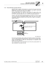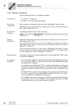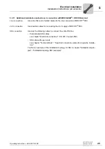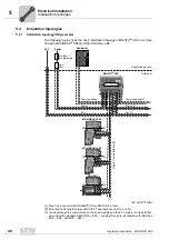
50
Operating Instructions – MOVIFIT® FDC
5
Standard ABOX "MTA...-S04.-...-00"
Electrical Installation
5.6
Standard ABOX "MTA...-S04.-...-00"
5.6.1
Description
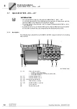
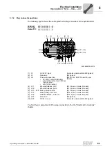
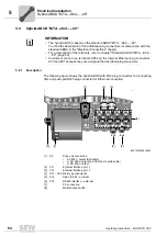
The following figure depicts the standard ABOX "MTA...-S04.-...-00" with terminals and
cable bushings:
5.6.2
Screw fittings
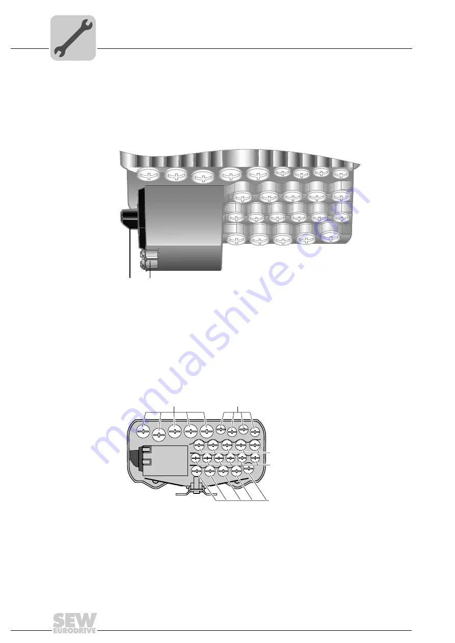
The following figure depicts the screw fittings of the standard ABOX:
3045820427
[1] Maintenance switch
[2] PE connection
[2]
[1]
27021600809749131
*) Communication via EtherNet/IP and Modbus/TCP is in preparation.
M25
M16
M20
M20
M16
PROFINET
EtherNet/IP
Modbus/TCP
MTA11A-503-S043-...-00
MTA11A-503-S043-...-00
MTA11A-503-S043-...-00
Summary of Contents for MOVIFIT FDC
Page 2: ...SEW EURODRIVE Driving the world...
Page 137: ...Operating Instructions MOVIFIT FDC 137 Index Y Y adapter 77 0 9 24 V terminals connection 55...
Page 138: ......
Page 139: ......

