Operating Instructions – MOVIFIT® FDC
95
7
Status LEDs of MOVIFIT
®
FDC
Operation
7
Operation
7.1
Status LEDs of MOVIFIT
®
FDC
7.1.1
General LEDs
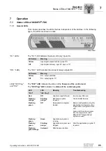
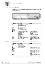
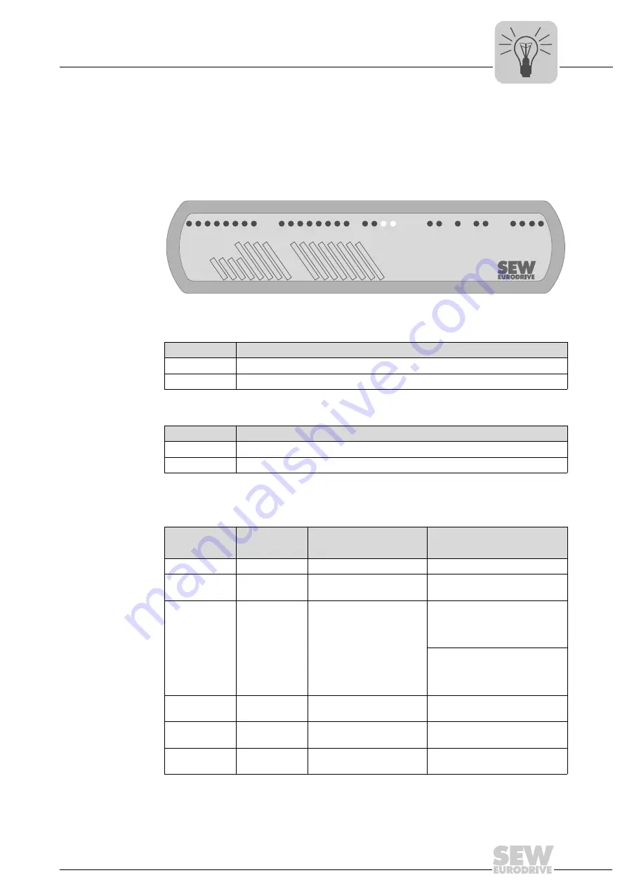
This chapter describes the LEDs that are independent of the fieldbus. In the following
figure, the LEDs are shown as dark:
"DI.." LEDs
The "DI.." LED indicates the status of binary inputs DI..
"DO.." LEDs
The "DO.." LED indicates the status of binary outputs DO..
LEDs "IEC Prog"
and "PLC"
The
"PLC" LED
indicates the status of the
firmware of the control card
.
The
"IEC Prog" LED
indicates the
status of the control program
.
2991635851
DI03/DO03
DI01/DO01
DI02/DO02
DI00/DO00
DI04DI05DI06DI07
DI08DI09DI10DI1
1
DI12DI13DI14DI15
IEC Prog
PLC
CANNET
24V_C Eng-EUSR
L1 A1 L2 A2
BF/NSRUN/MS
MOVIFIT
®
FDC
LED status
Meaning
Yellow
Input signal present at binary input DI..
Off
Input signal at binary input DI.. open or "0".
LED status
Meaning
Yellow
DO.. output switched.
Off
DO.. output logical "0"
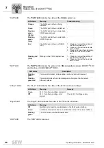
LED
LED
Meaning
Troubleshooting
"PLC"
"IEC Prog"
Red
Off
Unable to read SD card.
Insert a new SD card.
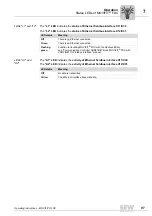
Flashing
orange
Flashing
orange
Bootloader update
required.
Contact SEW Service.
Flashing
green
Off
No application program
loaded.
Make a configuration using the
Application Configurator. (See
"Application Configurator" man-
ual)
Load an IEC control program
into the control card. (See
MOVI-PLC
®
Programming"
system manual)
Flashing
green
Green
Application program is
running.
–
Flashing
green
Flashing
orange
Application program was
stopped.
Start the application program if
required.
Flashing
green/orange
Irrelevant
Data backup is active.
–
Summary of Contents for MOVIFIT FDC
Page 2: ...SEW EURODRIVE Driving the world...
Page 137: ...Operating Instructions MOVIFIT FDC 137 Index Y Y adapter 77 0 9 24 V terminals connection 55...
Page 138: ......
Page 139: ......


