96
Operating Instructions – MOVIFIT® FDC
7
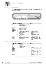
Status LEDs of MOVIFIT
®
FDC
Operation
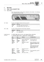
"CAN" LED
The
"CAN" LED
indicates the status of the
CAN 2
system bus.
"NET" LED
The
"NET" LED
indicates the status of the
SNI connection
between MOVIFIT
®
FDC
and the drive unit (MOVIGEAR
®
/ DRC).
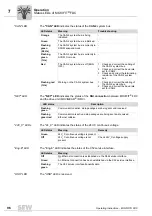
"24V_C" LEDs
The "24_C" LED indicates the status of the 24V-C continuous voltage.
"Eng-E" LED
The "Eng-E" LED indicates the status of the X52 service interface.
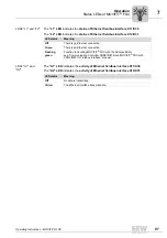
"USR" LED
The "USR" LED is reserved.
LED status
Meaning
Troubleshooting
Orange
The CAN 2 system bus is being
initialized.
-
Green
The CAN 2 system bus is initialized.
-
Flashing
green
(0.5 Hz)
The CAN 2 system bus is currently in
SCOM suspend mode.
-
Flashing
green
(1 Hz)
The CAN 2 system bus is currently in
SCOM On mode.
-
Red
The CAN 2 system bus is off (BUS-
OFF).
1. Check and correct the cabling of
the CAN 2 system bus.
2. Check and correct the baud rate
set for CAN 2.
3. Check and correct the terminating
resistors of the CAN 2 system
bus.
Flashing red
(1 Hz)
Warning on the CAN 2 system bus.
1. Check and correct the cabling of
the CAN 2 system bus.
2. Check and correct the baud rate
set for CAN 2.
LED status
Description
Flashing
green
Communication active; data packages are being sent and received.
Flashing
green/red
Communication is active; data packages are being sent and received,
Ethernet collision.
LED status
Meaning
Remedy
Green
24V_C continuous voltage is present
-
Off
24V_C continuous voltage is not
present
Check 24V_C voltage supply.
LED status
Meaning
Off
No Ethernet connection is established via the X52 service interface.
Green
An Ethernet connection has been established via the X52 service interface.
Flashing
green
The X52 service interface transmits data.
Summary of Contents for MOVIFIT FDC
Page 2: ...SEW EURODRIVE Driving the world...
Page 137: ...Operating Instructions MOVIFIT FDC 137 Index Y Y adapter 77 0 9 24 V terminals connection 55...
Page 138: ......
Page 139: ......

