108
Operating Instructions – MOVIFIT® FDC
9
Interfaces
Technical Data
9.5
Interfaces
9.5.1
SBus interface
9.5.2
RS485 interface
9.5.3
USB service interface
9.5.4
Ethernet service interface
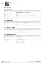
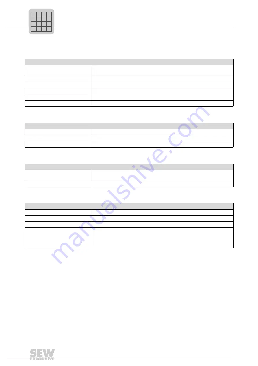
SBus
SBus interface
Interface to other SBUS-capable SEW units
CAN bus to CAN specification 2.0, parts A and B
Connection technology
M12, terminals
Transmission technology
ISO 11898 compliant
Bus termination
120
Ω
terminating resistor can be activated using DIP switch S3 (ABOX).
CAN interface sensor supply
DC 5 V
Rated current
max. 100 mA
RS485 interface
RS485 interface
Electrically isolated from MOVIFIT
®
electronics
Connection technology
M12, terminals
Standard
RS485 to EIA standard (with integrated dynamic terminating resistor)
USB
USB service interface
Service interface, not electrically isolated from MOVIFIT
®
electronics
according to USB-2.0 specification
Connection technology
USB socket, type B (on the EBOX)
EtherNet/IP
Automatic baud rate detection
10 MBd / 100 MBd
Connection technology
RJ45 (on the EBOX)
Maximum line length
100 m according to IEEE 802.3
Addressing
4 byte IP address or MAC ID (00-0F-69-xx-xx-xx)
IP address: 192.168.10.4
Subnet mask: 255.255.255.0
Standard gateway: 192.168.10.1
P
i
f
kVA
Hz
n
Summary of Contents for MOVIFIT FDC
Page 2: ...SEW EURODRIVE Driving the world...
Page 137: ...Operating Instructions MOVIFIT FDC 137 Index Y Y adapter 77 0 9 24 V terminals connection 55...
Page 138: ......
Page 139: ......


