Operating Instructions – MOVIFIT® FDC
47
5
Installation topologies
Electrical Installation
5.4.2
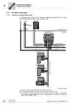
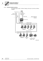
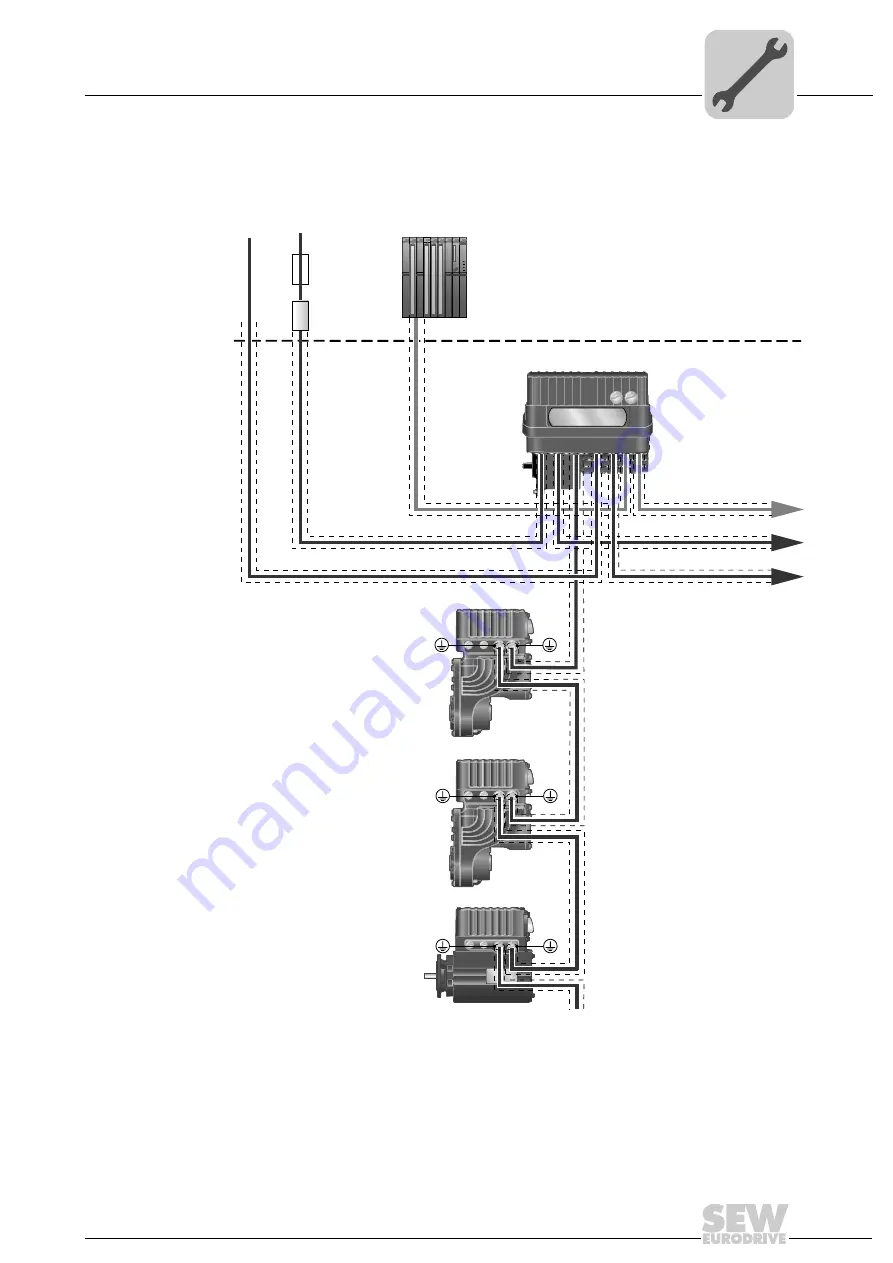
Installation topology SBus (example)
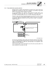
The following figure shows the basic SBus installation topology of MOVIFIT
®
FDC in
conjunction with MOVIGEAR
®
DSC and DRC-DSC drive units:
5595276683
[1] Permitted cable length between MOVIFIT
®
and last drive unit when using the recommended
hybrid cable:
•
1 MBaud: 25 m
•
500 kBd: 50 m
[2] Looping through the communication, the power supply and the 24 V supply is only permitted
when using the standard ABOX MTA...-S04-... Looping through is in preparation for ABOXes
MTA...-S54-.. and MTA...-S64-...
Control cabinet level
Field level
Communication
Communication [2]
Power
24 V
Power [2]
24 V [2]
Power
24 V
Hybrid cable (power + SBus)
[1]
MOVIGEAR
®
DSC
MOVIGEAR
®
DSC
DRC-DSC
MOVIFIT FDC
®
Controller
Line
filter
Pre-fuse /
line protection
Summary of Contents for MOVIFIT FDC
Page 2: ...SEW EURODRIVE Driving the world...
Page 137: ...Operating Instructions MOVIFIT FDC 137 Index Y Y adapter 77 0 9 24 V terminals connection 55...
Page 138: ......
Page 139: ......

