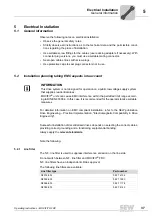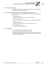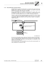
Operating Instructions – MOVIFIT® FDC
51
5
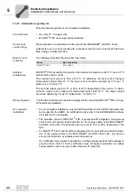
Standard ABOX "MTA...-S04.-...-00"
Electrical Installation
5.6.3
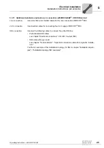
Additional installation instructions for "MTA...-S04.-...-00"
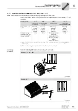
Permitted connection cross-section and current carrying capacity of the terminals
During installation, observe the permitted cable cross sections of the MOVIFIT
®
FDC
terminals:
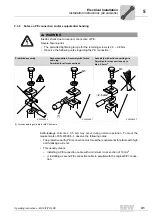
Activating
terminals
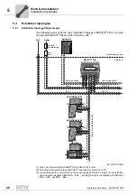
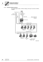
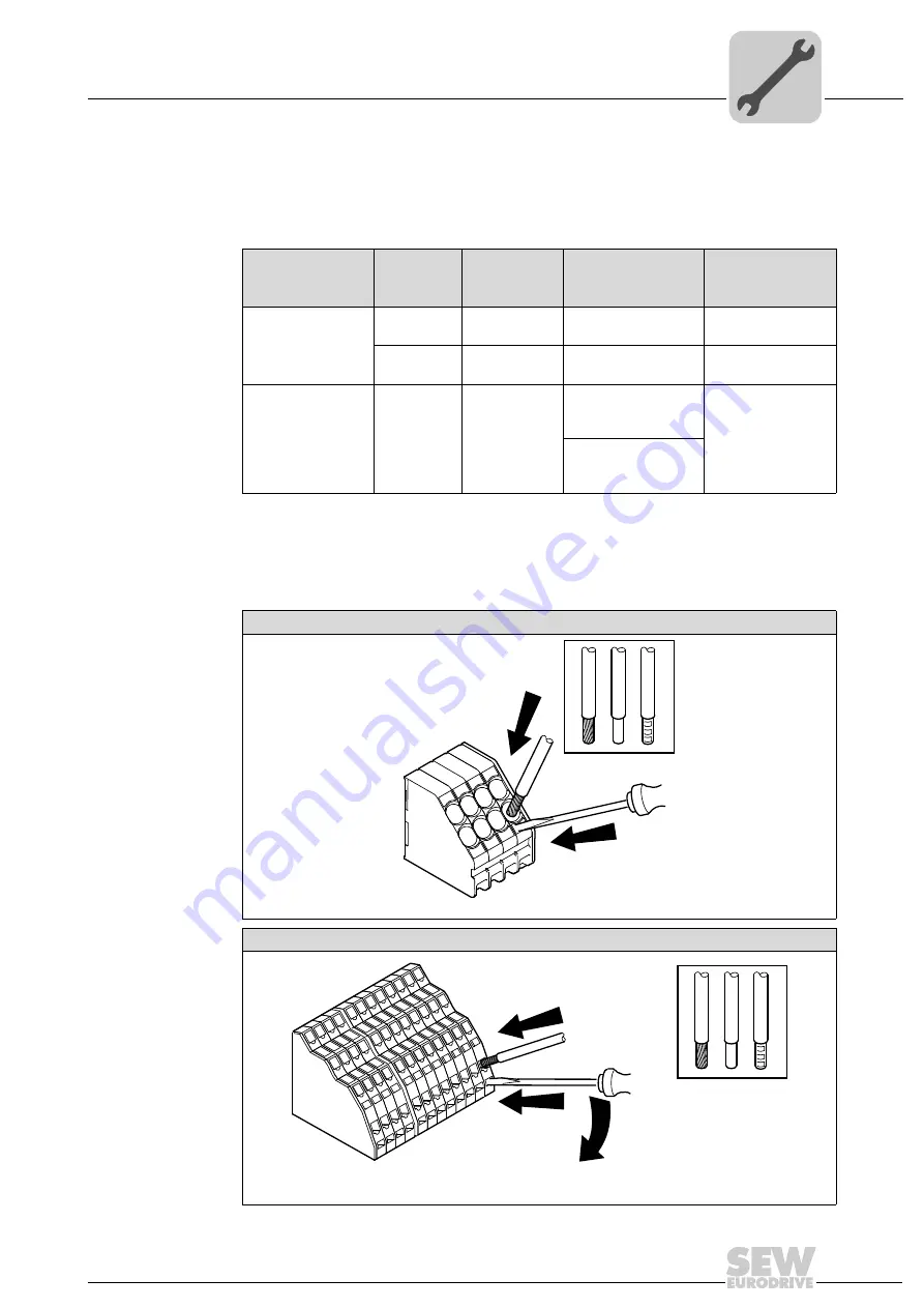
Note the following information for actuating the terminals:
Terminal data
X1
1)
1) When using conductor end sleeves, the permitted cross section is reduced by one unit (e.g. 2.5 mm
2
to
1.5 mm
2
)
X20
Supply sys-
tem cable
External 24 V
supply
I/O terminals
Terminal
MOVIGEAR
®
/ DRC
Connection cross
section
0.2 mm
2
–
10 mm
2
0.2 mm
2
–
6 mm
2
0.08 mm
2
–
2.5 mm
2
0.2 mm
2
–
6 mm
2
AWG 24 –
AWG 8
AWG 24 –
AWG 10
AWG 28 –
AWG 14
AWG 24 –
AWG 10
Current carrying
capacity (max. con-
tinuous current)
2)
2) The current carrying capacity indicates the value for the entire current path.
40 A
16 A
150 mA per sensor
connection
Total current 1.5 A
20 A
500 mA per binary
output
Total current 2.0 A
Terminals X1 / X8 / X20
344727819
Terminal X25
344724491
2.
1.
2.
1.
3.
Summary of Contents for MOVIFIT FDC
Page 2: ...SEW EURODRIVE Driving the world...
Page 137: ...Operating Instructions MOVIFIT FDC 137 Index Y Y adapter 77 0 9 24 V terminals connection 55...
Page 138: ......
Page 139: ......

