58
Operating Instructions – MOVIFIT® FDC
5
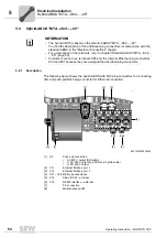
Standard ABOX "MTA...-S04.-...-00"
Electrical Installation
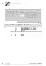
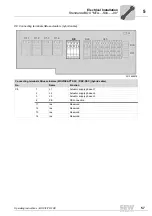
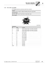
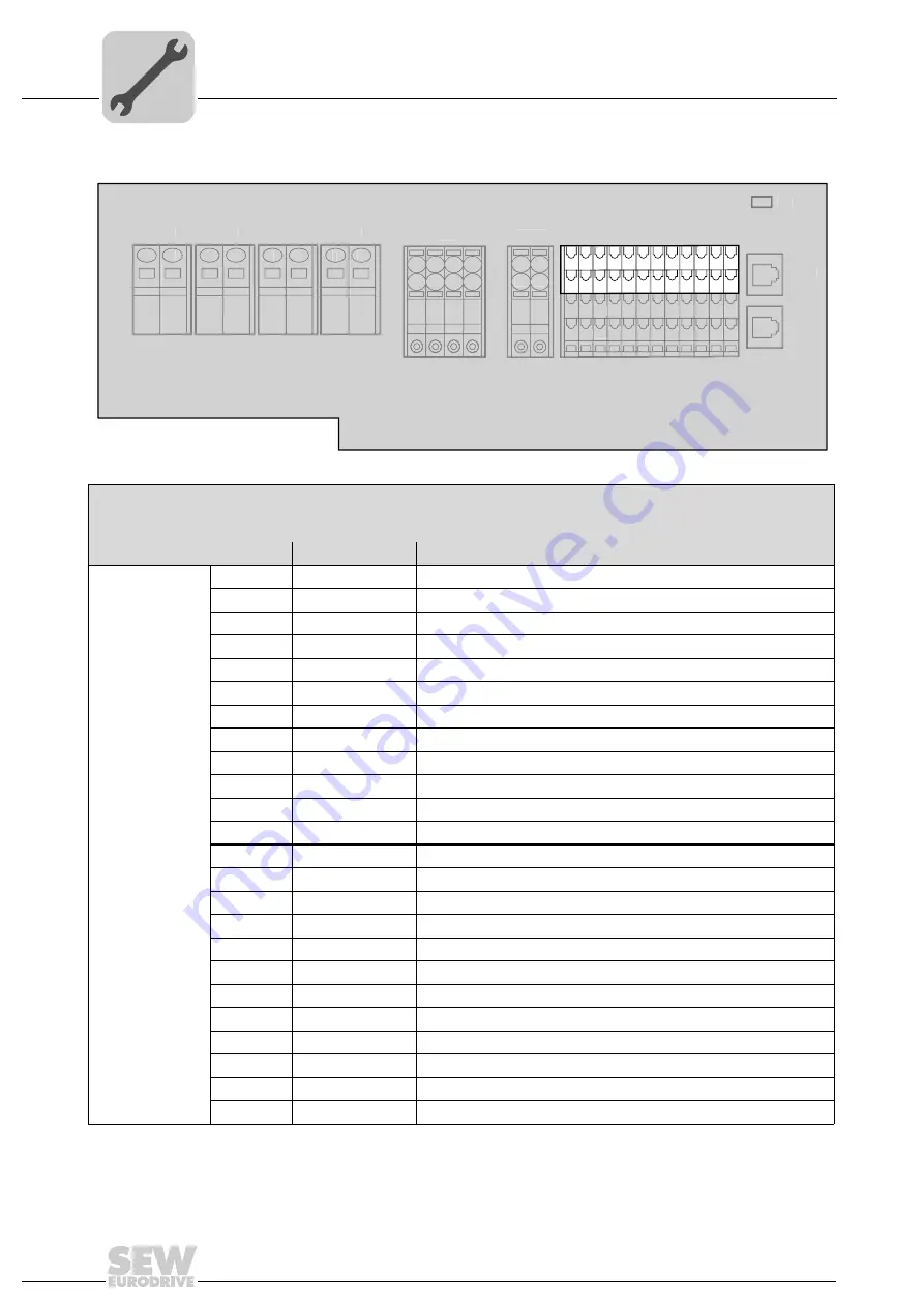
X25: I/O SBus RS485 terminals
3012854923
I/O terminals (connection of s actuators)
SBus terminal (CAN)
RS485 terminals
No.
Name
Function
X25
1
DI00 / DO00
Binary input DI00 (switching signal) and binary output DO00
2
DI02 / DO02
Binary input DI02 (switching signal) and binary output DO02
3
DI04
Binary input DI04 (switching signal)
4
D06
Binary input DI06 (switching signal)
5
DI08
Binary input DI08 (switching signal)
6
DI10
Binary input DI10 (switching signal)
7
DI12
Binary input DI12 (switching signal)
8
DI14
Binary input DI14 (switching signal)
9
CAN_H
CAN data line (high)
10
CAN_GND
Reference potential for CAN data line
11
RS+
RS485 data line (+)
12
Res.
Reserved
15
DI01 / DO01
Binary input DI01 (switching signal) and binary output DO01
16
DI03 / DO03
Binary input DI03 (switching signal) and binary output DO03
17
DI05
Binary input DI05 (switching signal)
18
DI07
Binary input DI07 (switching signal)
[19]
DI09
Binary input DI09 (switching signal)
20
DI11
Binary input DI11 (switching signal)
21
DI13
Binary input DI13 (switching signal)
22
DI15
Binary input DI15 (switching signal)
23
CAN_L
CAN data line (low)
24
Res.
Reserved
25
RS-
RS485 data line (-)
26
Res.
Reserved
X8
4
3
2
1
14
13
12
11
X20
2
1
12
11
X1.3
X1.4
X1.2
X1.1
1
2
1
2
1
2
1
2
S3
X31
X30
15
1 2 3 4 5 6 7 8
16171819202122
454647
303132
4849505152
3334353637
9
23
53
38
10
24
54
39
11
25
55
40
12
26
56
41
X8
4
3
2
1
14
13
12
11
X20
2
1
12
11
X1.3
X1.4
X1.2
X1.1
1
2
1
2
1
2
1
2
S3
X31
X30
15
1 2 3 4 5 6 7 8
16171819202122
454647
303132
4849505152
3334353637
9
23
53
38
10
24
54
39
11
25
55
40
12
26
56
41
X25
15
1 2 3 4 5 6 7 8
16171819202122
9
23
10
24
11
25
12
26
Summary of Contents for MOVIFIT FDC
Page 2: ...SEW EURODRIVE Driving the world...
Page 137: ...Operating Instructions MOVIFIT FDC 137 Index Y Y adapter 77 0 9 24 V terminals connection 55...
Page 138: ......
Page 139: ......

