Operating Instructions – MOVIFIT® FDC
63
5
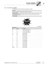
Hybrid ABOX "MTA...-S54.-...-00"
Electrical Installation
5.7.2
Plug connector positions
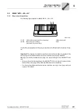
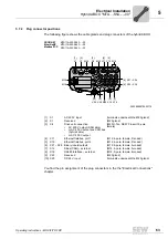
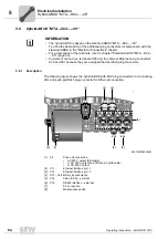
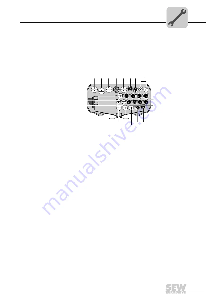
The following figure shows the cable glands and plug connectors of the hybrid ABOX:
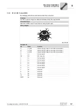
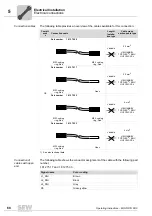
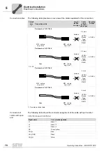
You find the pin assignment of the plug connectors in the the "Electrical Connections"
chapter.
36028800070920715
[1] X1
AC 400 V input
(terminals underneath the M25 gland)
[2] X1
Reserved
(M25 gland)
[3] X8
Drive unit connection
•
AC 400 V output (SNI cable)
•
or AC 400 V output and CAN bus
(hybrid cable)
•
or AC 400 V output
(M23 H-Tec, SEW P insert 15-pole,
female)
[4] X11
Ethernet fieldbus, port 1
(M12, 4-pole, female, D-coded)
[5] X12
Ethernet fieldbus, port 2
(M12, 4-pole, female, D-coded)
[6] X21 – X28 Binary inputs/outputs
(M12, 5-pole, female, A-coded)
[7] X14
SBus (CAN) – external
(M12, 5-pole, female, A-coded)
[8] X16
RS485 interface – external
(M12, 5-pole, female, B-coded)
[9] X20
Reserved
(M20 gland)
[10] X20
DC 24 V input
(terminals underneath the M20 gland)
[1]
X1
M16
M20
[6] X21 – X24
[6] X25 – X28
[7]
X14
[8]
X16
[9]
X20
[10]
X20
M20
M16
PROFINET
EtherNet/IP
Modbus/TCP
MTA11A-503-S543-...-00
MTA11A-503-S543-...-00
MTA11A-503-S543-...-00
[2]
X1
M25
[3]
X8
M25
[4]
X11
[5]
X12
Summary of Contents for MOVIFIT FDC
Page 2: ...SEW EURODRIVE Driving the world...
Page 137: ...Operating Instructions MOVIFIT FDC 137 Index Y Y adapter 77 0 9 24 V terminals connection 55...
Page 138: ......
Page 139: ......

