background image

Operating Instructions – MOVIFIT® FDC 

65

5

Hybrid-ABOX "MTA...-S64.-...-00"

Electrical Installation

5.8.2

Plug connector positions

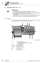
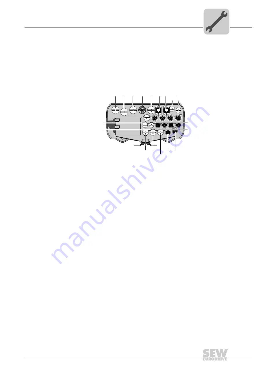
The following figure shows the cable glands and plug connectors of the hybrid ABOX:

You find the pin assignment of the plug connectors in the the "Electrical Connections"
chapter.

27021600817498635

[1] X1

AC 400 V input 

(terminals underneath the M25 gland)

[2] X1

Reserved

(M25 gland)

[3] X8

Drive unit connection

AC 400 V output (SNI cable) 

or AC 400 V output and CAN bus 

(hybrid cable)

or AC 400 V output

(M23 H-Tec, SEW P insert 15-pole, 

female)

[4] X11

Ethernet fieldbus, port 1

(Han

®

 3 A RJ45)

[5] X12

Ethernet fieldbus, port 2

(Han

®

 3 A RJ45)

[6] X21 – X28 Binary inputs/outputs

(M12, 5-pole, female, A-coded)

[7] X14

SBus (CAN) – external

(M12, 5-pole, female, A-coded)

[8] X16

RS485 interface – external

(M12, 5-pole, female, B-coded)

[9] X20

Reserved

(M20 gland)

[10] X20

DC 24 V input

(terminals underneath the M20 gland)

M20

M16

[1]

X1

M16

[6]  X21 – X24

[6]  X25 – X28

[2]

X1


M25

[3]

X8


M25

[4]

X11

[5]

X12

PROFINET

EtherNet/IP

Modbus/TCP

MTA11A-503-S643-...-00

 
M20

[7]

X14

[8]

X16

[9]

X20

[10]

X20

Summary of Contents for MOVIFIT FDC

Page 1: ...Drive Technology Drive Automation System Integration Services Operating Instructions Decentralized Drive Controller MOVIFIT FDC Edition 10 2012 19471211 EN...

Page 2: ...SEW EURODRIVE Driving the world...

Page 3: ...OX active electronics unit 13 3 4 ABOX passive connection unit 17 3 5 Version for wet areas corrosion protection optional 19 3 6 Type designation MOVIFIT FDC 21 4 Mechanical Installation 23 4 1 Genera...

Page 4: ...s LEDs of MOVIFIT FDC 95 8 Service 100 8 1 Unit diagnostics 100 8 2 Unit replacement 100 8 3 SEW Electronics Service 102 8 4 Storage 103 8 5 Disposal 103 9 Technical Data 104 9 1 CE marking and UL app...

Page 5: ...of damage to property and other notes 1 2 2 Structure of the section related safety notes Section related safety notes do not apply to a specific action but to several actions per taining to one subj...

Page 6: ...f liability You must comply with the information contained in this documentation to ensure safe operation and to achieve the specified product characteristics and performance fea tures SEW EURODRIVE a...

Page 7: ...2 2 General information Never install damaged products or take them into operation Submit a complaint to the shipping company immediately in the event of damage During operation MOVIFIT FDC and the c...

Page 8: ...information on the connection requirements as provided on the nameplate and in the documentation 2 4 1 Safety functions MOVIFIT FDC and the connected MOVIGEAR and DRC drive units may not perform safe...

Page 9: ...ical Data 2 8 Electrical connection Observe applicable national accident prevention guidelines e g BGV A3 when working on a live MOVIFIT FDC unit Perform electrical installation according to the perti...

Page 10: ...specified in the technical data chapter applies only if the EBOX is installed on the ABOX Never disconnect power plug connectors during operation Doing so can lead to danger ous electric arcs forming...

Page 11: ...1 Features of MOVIFIT FDC MOVIFIT FDC is characterized by the following features Up to 10 SNI actuators or 16 SBus actuators can be connected Single Line Network Installation SNI and or SBus communic...

Page 12: ...he hybrid ABOX EBOX ABOX Variant MTC 00 MOVIFIT FDC for controlling MOVIGEAR and DRC drive units ABOX MTA S04 0 Standard ABOX with terminals and cable bushings MTA S54 00 Hybrid ABOX with M23 plug con...

Page 13: ...13 reserved Do not change the DIP switch setting 6 DIP switch S11 reserved Do not change the DIP switch setting 7 DIP switch S12 for selecting the communication protocol PROFINET or EtherNet IP 8 SD m...

Page 14: ...protection of MOVIFIT FDC and enables easy access MOVIFIT FDC is available with the following memory cards When using the SD memory card OMC41B T you can freely set the parameters for MOVIFIT FDC Whe...

Page 15: ...CU standard The performance class CCU standard is intended for application modules with single axis functionality and medium response times A maximum of 16 axes max 10 of them SNI axes can be connecte...

Page 16: ...the control of demanding applications such as material handling Performance class MOVI PLC standard The control card of the performance class MOVI PLC standard enables coordinated single axis movemen...

Page 17: ...on unit The following figure shows the MOVIFIT standard ABOX MTA S04 00 as an ex ample 3041002251 1 Mounting rail 2 Connection to EBOX 3 Protection cover 4 DIP switch S3 for SBus bus termination 5 Gro...

Page 18: ...NING Electric shock due to dangerous voltages present in the ABOX Severe or fatal injuries Disconnect the power interface from the power supply before you perform any work on the unit Observe a minimu...

Page 19: ...ousing closed and all cable entries and plug connection sealed according to the relevant degree of protection Easy to clean housing self draining design Specially treated surface with anti stick prope...

Page 20: ...treatment 8 ABOX with special surface treatment available only in one color 9 Maintenance switch 10 Stainless steel screw plugs optionally available 10 Y Y 9 ABOX MTA13 S04 00 EBOX MTC13 00 DI 03 DI...

Page 21: ...07 B 1 Internal nameplate EBOX status field A B 1 1 MT C 11 A 000 503 R9500 00 EBOX variant 00 Series Performance class type SD card R95 OMC41B T0 CCU standard parameterizable R96 OMH41B T0 MOVI PLC s...

Page 22: ...00 Series Maintenance switch M16 Load disconnector line protection up to 15 A M20 Load disconnector line protection up to 20 A Fieldbus 3 PROFINET IO EtherNet IP Modbus TCP Connection configuration S...

Page 23: ...elements observe the applicable standards the technical data of the unit and the local circumstances 4 2 Permitted mounting position The following figure shows the permitted mounting positions for MOV...

Page 24: ...for the standard mounting rail You find detailed dimension drawings in the Dimension drawings page 115 chapter 9007202299435147 66 334 5 303 5 280 140 37 9 min 40 15 min 50 1 2 7 0 6x 13 9 6x INFORMA...

Page 25: ...007202299484811 334 4 66 min 40 min 50 1 2 15 37 9 40 50 50 7 0 8x 13 9 8x INFORMATION 1 Observe the minimum installation clearance so that the EBOX can be removed from the ABOX 2 Observe the minimum...

Page 26: ...t least 4 screws on the mounting surface Use appropriate washers or screw and washer assemblies for the mounting plates with special surface treatment for versions used in wet areas WARNING Risk of cr...

Page 27: ...Operating Instructions MOVIFIT FDC 27 4 Mounting Mechanical Installation 3 Hang the ABOX with the mounting rail into the screws 3045024523 1 2...

Page 28: ...structions MOVIFIT FDC 4 Mounting Mechanical Installation 4 Tighten the screws CAUTION Risk of injury if the load falls Minor injuries Tighten at least 4 wall screws to ensure a secure fit after mount...

Page 29: ...further up 2 Remove the EBOX from the ABOX by lifting it upwards Do not twist the EBOX WARNING Danger of burns due to hot surfaces of the MOVIFIT unit Severe injuries Do not touch the MOVIFIT until i...

Page 30: ...orce when closing the MOVIFIT unit The central opening closing mechanism may be damaged as a result Make sure that the gasked is properly seated in the groove of the EBOX This means that the gasket is...

Page 31: ...Tighten the retaining screw with a maximum tightening torque of 7 Nm 60 lb in If there is a noticeable counter torque remove the EBOX again and check to see that the gasket is seated properly If neces...

Page 32: ...MOVIFIT FDC 4 Tightening torques Mechanical Installation 4 5 Tightening torques 4 5 1 Blanking plugs Tighten the blanking plugs included in the delivery of SEW EURODRIVE with a tighten ing torque of...

Page 33: ...e from the cable gland Cable with outer diameter 10 mm 160 N Cable with outer diameter 10 mm 100 N 758624523 Screw fitting Part number Size Tightening torque EMC cable glands nickel plated brass 1 820...

Page 34: ...c screw plugs delivered as standard with suitable stainless steel screws page 110 Note the permitted mounting position page 23 Make sure to install the cable with a drip loop see the following figure...

Page 35: ...t areas Screw plugs Tighten the screw plugs optionally supplied by SEW EURODRIVE to 2 5 Nm 22 lb in INFORMATION When using the version for wet areas replace the plastic screw plugs delivered as standa...

Page 36: ...le gland Cable with outer diameter 10 mm 160 N Cable with outer diameter 10 mm 100 N 512772875 Screw fitting Part number Size Tightening torque EMC cable glands nickel plated brass 1820 478 3 M16 x 1...

Page 37: ...Practical Implementation Electromagnetic Compatibility in Drive Engineering Successful installation of decentralized drives depends on selecting the correct cables providing correct grounding and a f...

Page 38: ...data lines for equipotential bonding Establish a connection over a wide surface area between the MOVIFIT mounting rail and the system Untreated unpainted uncoated mounting surface To do so use a grou...

Page 39: ...ated SNI cable see chapter Electrical connections X8 AC 400 V output SNI SNI cable with open ends see chapter Technical Data Specified connection cables for single line installa tion Prefabricated hyb...

Page 40: ...ODRIVE recommends that you do not use RCDs However if a residual current device is stipulated for direct or indirect protection against contact observe the following note in accordance with EN 61800 5...

Page 41: ...g a PE connection cable with a minimum cross section of 10 mm2 or installing a second PE connection cable in parallel with the original PE connec tion WARNING Electric shock due to incorrect connectio...

Page 42: ...ing instructions Above 2000 m above sea level the air distances are only sufficient for overvoltage class 2 If installed at altitudes higher than 2000 m above sea level you have to install additional...

Page 43: ...that no more than 15 A or 20 A of total current runs through the connected MOVIGEAR and DRC drive units For UL compli ant installation additional restrictions must be observed see chapter UL compliant...

Page 44: ...ut current rating at temperatures higher than 40 C the output current should be derated by 3 per C between 40 C and 60 C Wiring diagrams You find the terminal and connector assignment for connecting M...

Page 45: ...FDC 24 V connection Use shielded cables for connecting the 24 V supply of MOVIFIT FDC SNI connection Use only the following cables to connect the entire SNI line Prefabricated SNI cables see chapter...

Page 46: ...its MOVIGEAR SNI or DRC SNI in total 2 Permitted cable length between MOVIFIT and last drive unit max 100 m 3 Looping through the communication the power supply and the 24 V supply is only permitted w...

Page 47: ...MOVIFIT and last drive unit when using the recommended hybrid cable 1 MBaud 25 m 500 kBd 50 m 2 Looping through the communication the power supply and the 24 V supply is only permitted when using the...

Page 48: ...combined topology with single line network and SBus installation 5978456843 PLC 24 V Line filter Pre fuse line protection PowerPower MOVIGEAR SNI MOVIFIT FDC Electronic motor DRC SNI Single Line SNI...

Page 49: ...rew plugs of the USB and Ethernet service interface are properly installed Missing or incorrectly installed screw plugs can cause damage to the MOVIFIT FDC unit Once you have finished working on the M...

Page 50: ...OX MTA S04 00 with terminals and cable bushings 5 6 2 Screw fittings The following figure depicts the screw fittings of the standard ABOX 3045820427 1 Maintenance switch 2 PE connection 2 1 2702160080...

Page 51: ...conductor end sleeves the permitted cross section is reduced by one unit e g 2 5 mm2 to 1 5 mm 2 X20 X25 1 X8 1 Supply sys tem cable External 24 V supply I O terminals Terminal MOVIGEAR DRC Connection...

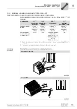
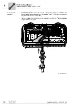
Page 52: ...SEW EURODRIVE recommends using the appropriately stripped and prefabricated SNI cables specifically designed for connecting MOVIFIT FDC with the SNI actua tors MOVIGEAR SNI or DRC SNI The cable shield...

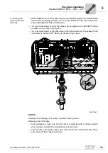
Page 53: ...to the MOVIFIT ABOX as follows using an EMC cable gland The inner cable shield of the CAN cable in the hybrid cable must be applied to the shield plate of the MOVIFIT ABOX as follows using a clamp NOT...

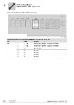
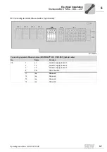
Page 54: ...MOVIFIT FDC using a suitable external disconnecting device and wait at least 5 minutes before opening the wiring space 3010522635 Line terminal power bus No Name Function X1 1 1 L1 Supply system phas...

Page 55: ...3132 4849505152 3334353637 9 23 53 38 10 24 54 39 11 25 55 40 12 26 56 41 X25 X1 3 X1 4 X1 2 X1 1 1 2 1 2 1 2 1 2 S3 X8 4 3 2 1 14 13 12 11 X31 X30 15 1 2 3 4 5 6 7 8 16171819202122 454647 303132 4849...

Page 56: ...mmunication 3 L3_SNI Actuator supply phase L3 with SNI communication 4 PE PE connection 11 res Reserved 12 res Reserved 13 res Reserved 14 res Reserved X20 2 1 12 11 X1 3 X1 4 X1 2 X1 1 1 2 1 2 1 2 1...

Page 57: ...L3 Actuator supply phase L3 4 PE PE connection 11 res Reserved 12 res Reserved 13 res Reserved 14 res Reserved X20 2 1 12 11 X1 3 X1 4 X1 2 X1 1 1 2 1 2 1 2 1 2 S3 X31 X30 15 1 2 3 4 5 6 7 8 16171819...

Page 58: ...I01 DO01 Binary input DI01 switching signal and binary output DO01 16 DI03 DO03 Binary input DI03 switching signal and binary output DO03 17 DI05 Binary input DI05 switching signal 18 DI07 Binary inpu...

Page 59: ...ference potential 46 GND Reference potential 47 GND Reference potential 48 GND Reference potential 49 GND Reference potential 50 GND Reference potential 51 GND Reference potential 52 GND Reference pot...

Page 60: ...12 11 15 1 2 3 4 5 16171819 454647 303132 8 22 7 21 6 20 4849505152 3334353637 9 23 53 38 10 24 54 39 11 25 55 40 12 26 56 41 X25 S3 X31 X30 Function Ethernet fieldbus plug connector PROFINET IO Ethe...

Page 61: ...TA S04 00 Electrical Installation The following figure shows the Ethernet connection in the ABOX 3440787979 X30 X30 X31 X31 X30 X31 INFORMATION Angular RJ45 connectors cannot be used to connect the Et...

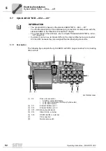
Page 62: ...chapter For a description of the terminals refer to chapter Standard ABOX MTA S02 00 page 50 Customers cannot use terminals X25 and the internal Ethernet plug connectors X30 and X31 because they are...

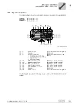
Page 63: ...r AC 400 V output and CAN bus hybrid cable or AC 400 V output M23 H Tec SEW P insert 15 pole female 4 X11 Ethernet fieldbus port 1 M12 4 pole female D coded 5 X12 Ethernet fieldbus port 2 M12 4 pole f...

Page 64: ...e Electrical Connections chapter For a description of the terminals refer to chapter Standard ABOX MTA S02 00 page 50 Customers cannot use terminals X25 and the internal Ethernet plug connectors X30 a...

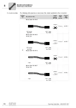
Page 65: ...t SNI cable or AC 400 V output and CAN bus hybrid cable or AC 400 V output M23 H Tec SEW P insert 15 pole female 4 X11 Ethernet fieldbus port 1 Han 3 A RJ45 5 X12 Ethernet fieldbus port 2 Han 3 A RJ45...

Page 66: ...hey are described in the following sections Specify the part number and length of the required cable in your order The number and design of the required connection cables depend on the design of the u...

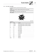
Page 67: ...coding ring red violet Wiring diagram 2497125387 Assignment No Name Function A L1_SNI Actuator supply phase L1 with SNI communication B L2_SNI Actuator supply phase L2 with SNI communication C L3_SNI...

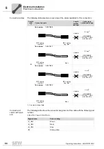
Page 68: ...Connection cable Length Installa tion type Cable cross section cable type CE Part number 1 812 750 9 Variable 2 5 mm2 HELUKABEL TOPFLEX EMV UV 2YSLCYK J M23 coding ring Red M23 coding ring Red Part n...

Page 69: ...et Wiring diagram 2749367179 Assignment No Name Function A L1 Actuator supply phase L1 B L2 Actuator supply phase L2 C L3 Actuator supply phase L3 D n c Not connected PE PE PE connection 1 n c Not con...

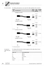
Page 70: ...section cable type Operating voltage CE UL Part number 1 812 742 8 Variable 2 5 mm2 LEONI Elocab Type EHRK 016281 AC 500 V M23 coding ring violet M23 coding ring violet Part number 1 812 743 6 Variab...

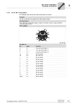
Page 71: ...ny Intercontec female coding ring Black protected against contact Wiring diagram 2497125387 Assignment No Name Function A L1 Line connection phase L1 B L2 Line connection phase L2 C L3 Line connection...

Page 72: ...Installa tion type Cable cross section Operat ing voltage CE Part number 1 812 746 0 Variable 2 5 mm2 AC 500 V M23 coding ring Black M23 coding ring Black Part number 1 813 395 9 Halogen free Variable...

Page 73: ...V M23 coding ring Black M23 coding ring Black Part number 1 813 397 5 Halogen free Variable 4 mm2 AC 500 V M23 coding ring Black M23 coding ring Black Part number 1 812 749 5 Variable 4 mm2 AC 500 V O...

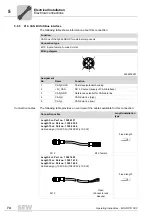
Page 74: ...816267 Assignment No Name Function 1 CAN_SHLD Shield equipotential bonding 2 5V_CAN DC 5 V output supply of CAN interface 3 CAN_GND Reference potential for CAN data line 4 CAN_H CAN data line high 5 C...

Page 75: ...142 9 5 9 6 X16 RS485 interface external The following table shows information about this connection Signal name Color coding CAN_SHLD Gray 5V_CAN Red GND Black CAN_H White CAN_L Blue Function RS485 i...

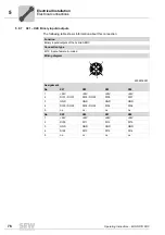
Page 76: ...ion Binary inputs outputs of the hybrid ABOX Connection type M12 5 pole female A coded Wiring diagram 2264816267 Assignment No X21 X22 X23 X24 1 24V 24V 24V 24V 2 DI01 DO01 DI03 DO03 DI05 DI07 3 GND G...

Page 77: ...tuators to an M12 plug connector use a Y adapter with extension The Y adapter is available from different manufacturers 915294347 Manufac turer Escha Type WAS4 0 3 2FKM3 1180380683 Manufac turer Binde...

Page 78: ...tions MOVIFIT engineering and diagnostics with MOVITOOLS MotionStudio Connection cable Use a commercially available USB cable with a type B USB plug Maximum permitted length of the USB cable 5 m Funct...

Page 79: ...vice interface X52 comprises the following functions MOVIFIT engineering and diagnostics with MOVITOOLS MotionStudio Function Ethernet service interface of the EBOX Connection type Ethernet RJ45 Wirin...

Page 80: ...TA S54 00 The following table informs about this connection Function Ethernet fieldbus interface of the hybrid ABOX MTA S54 00 PROFINET IO EtherNet IP Modbus TCP Connection type M12 4 pole female D co...

Page 81: ...line 3 RX Receive line 4 res Reserved 5 res Reserved 6 RX Receive line 7 res Reserved 8 res Reserved 1 8 NOTICE The RJ45 socket can be damaged by inserting commercially available RJ45 patch ca bles wi...

Page 82: ...1 See also technical data SNI cable Cable cross sec tion cable type CE Part number 1 330 330 9 Cable reel 30 m Cable reel 100 m Cable reel 200 m 2 5 mm2 HELUKABEL TOPFLEX EMV UV 2YSLCYK J Open cable e...

Page 83: ...hows available hybrid cables Hybrid cable Cable cross sec tion manufacturer Part no 1 328 477 0 Cable reel 30 m Cable reel 100 m Cable reel 200 m 2 5 mm2 LEONI Elocab Type EHRK 016281 Open cable end b...

Page 84: ...on example 1 The SBus master MOVIFIT FDC is located at the end of the SBus segment DIP switch S3 of the SBus master MOVIFIT FDC ON INFORMATION Connection example 1 applies in combination with the foll...

Page 85: ...ard ABOX MTA S04 00 4273650443 X 16 Number of connected SNI units 1 DIP switch S3 for bus termination 2 DIP switch for bus termination in the slave unit 3 EMC cable gland 3 3 SBus SLAVE 2 SBus SLAVE X...

Page 86: ...sing switch S3 The following table shows the operating principle of the bus termination switch Bus termination S3 ON Bus termination S3 OFF factory setting 4275935371 4275938571 Bus termination switch...

Page 87: ...of the wiring in accordance with applicable national standards Check the grounding Check the insulation between the supply system cable and the DC 24 V cable Check the insulation between supply syste...

Page 88: ...until it has cooled down sufficiently WARNING Uncontrolled unit behavior due to ineffective emergency stop circuit Severe or fatal injuries Comply with the installation notes The installation must onl...

Page 89: ...rcially available USB cable type B plug or commercially available Ethernet cable The following software is required on the PC or laptop MOVITOOLS MotionStudio version 5 8 or later You find more inform...

Page 90: ...switch S13 DIP switches S13 1 through S13 8 of the EBOX are set at the factory You are not allowed to change the setting of DIP switches S13 1 through S13 8 DIP switch S12 1 2 IP address allocation E...

Page 91: ...th Fieldbus Interface PROFINET IO manual 3 MOVITOOLS MotionStudio For information refer to chapter First steps with MOVITOOLS MotionStudio page 93 MOVI PLC Programming in the PLC Editor system manual...

Page 92: ...up green 3041009931 1 Commercially available Ethernet cable You have to configure the Ethernet interface to a fixed IP address 2 Commercially available USB cable type B The USB interface configures it...

Page 93: ...te with your units You find more detailed information in the Communication Controller DHR21B 41B and MOVIFIT FDC with PROFINET IO Fieldbus Interface manual 2 Scan your network unit scan To do so click...

Page 94: ...open the context menu and display the tools for configuring the unit 3 To open the Application Configurator choose Application Configurator from the menu 4 Configure the unit in the Application Confi...

Page 95: ...I E C P r o g P L C C A N N E T 2 4 V _ C E n g E U S R L 1 A 1 L 2 A 2 B F N S R U N M S MOVIFIT FDC LED status Meaning Yellow Input signal present at binary input DI Off Input signal at binary inpu...

Page 96: ...system bus is off BUS OFF 1 Check and correct the cabling of the CAN 2 system bus 2 Check and correct the baud rate set for CAN 2 3 Check and correct the terminating resistors of the CAN 2 system bus...

Page 97: ...ctivity of Ethernet fieldbus interface X11 X30 The A2 LED indicates the activity of Ethernet fieldbus interface X12 X31 LED status Meaning Off There is no Ethernet connection Green There is an Etherne...

Page 98: ...e PROFINET IO controller configuration is activated to visually localize the stations Red Connection to the PROFINET IO controller has failed PROFINET IO device does not detect a link Bus interruption...

Page 99: ...test Flashing green There is no controlling IO connection Green There is a controlling EtherNet IP or Modbus TCP connection Red Conflict detected in the assigned IP addresses Another station in the n...

Page 100: ...MOVIFIT FDC unit is mainly available on the PC laptop You find more detailed information in the Communication Controller DHR21B 41B and MOVIFIT FDC with PROFINET IO Fieldbus Interface manual INFORMAT...

Page 101: ...retaining screw 7 Switch on the MOVIFIT FDC unit with the new EBOX 8 The parameters saved on the card are now available again If required you can change the parameter set or save the changed unit dat...

Page 102: ...llowing information at hand when you consult the SEW Service Type designation 1 Serial number 2 Digits in the status field 3 Brief description of the application Nature of the fault Accompanying circu...

Page 103: ...connec tions with the protective caps supplied Make sure that the unit is not subject to mechanical impact during storage Connect the unit to the power supply for at least 5 minutes every 2 years Obs...

Page 104: ...ard EN 61800 3 Variable speed electrical drives Provided that you comply with the installation instructions the CE marking requirements for the entire machine system in which they are installed are sa...

Page 105: ...m at 500 kBaud max 50 m General information Interference immunity Meets EN 61800 3 Interference emission with EMC compliant installation According to limit value class C3 to EN 61800 3 Ambient temper...

Page 106: ...nding on the number and type of connected sensors Sensor supply X25 2 circuits Total current terminals 30 33 700 mA Total current terminals 34 37 700 mA Electrical isolation Separate potentials for Fi...

Page 107: ...iables retain 8 kB Engineering Engineering for all SEW components connected to MOVIFIT FDC is carried out via USB service interface X51 Ethernet service interface X52 Ethernet fieldbus interface X30 X...

Page 108: ...ated current max 100 mA RS485 interface RS485 interface Electrically isolated from MOVIFIT electronics Connection technology M12 terminals Standard RS485 to EIA standard with integrated dynamic termin...

Page 109: ...ection 10 MBd 100 MBd Connection technology 2 x M12 2 x RJ45 push pull or 2 x RJ45 plug connector in the ABOX Integrated switch Supports auto crossing auto negotiation Maximum line length 100 m accord...

Page 110: ...pc 1 822 371 0 RJ45 M12 Ethernet adapter RJ45 internal M12 external 2 required for each unit 1 pc 1 328 168 2 Screw plug for interfaces on the EBOX 1 pc 1 813 062 3 Type Figure Content Size Part numb...

Page 111: ...X EMV UV 2YSLCYK J HELUKABEL TOPFLEX EMV UV 2YSLCYK J UL CSA UL compliant installation HELUKABEL TOPFLEX EMV 2YSLCY J The following figure shows the cable structure HELUKABEL TOPFLEX EMV UV 3 PLUS 2YS...

Page 112: ...res show the cable structure LAPP LFLEX SERVO 2YSLCYK JB LAPP LFLEX SERVO 2YSLCY JB Black outer cable sheath UV resistant Transparent outer cable sheath 3336402059 2640950539 INFORMATION A high signal...

Page 113: ...E Colors Black with printed numbers 1 3 1 x yellow green 4 cores 4 0 mm 2 Conductor 228 x 0 15 mm blank copper Insulation TPE Colors Black with printed numbers 1 3 1 x yellow green 2 Filler 3 1 conduc...

Page 114: ...34 80 C 1000 V certified 80 C 600 V Operating voltage 1000 V Test voltage core core DC 4700 V Test voltage core shield DC 3110 V Test voltage shield Position 3 DC 3000 V spark test Operating temperatu...

Page 115: ...n drawings 9 9 1 MOVIFIT FDC with standard mounting rail 9007202299196811 1 The clearance of 104 mm below is only necessary for ABOXes with plug connector for connecting the drive unit 333 3 327 min 4...

Page 116: ...MOVIFIT FDC with optional stainless steel mounting rail M11 9007202299198731 1 The clearance of 104 mm below is only necessary for ABOXes with plug connector for connecting the drive unit 333 3 min 40...

Page 117: ...onnecting the drive units The following figure shows the minimum installation clearance of the hybrid ABOX with plug connector for connecting the drive units 5633883019 1 Smallest permitted pending ra...

Page 118: ...KG Ernst Blickle Stra e 42 D 76646 Bruchsal declares under sole responsibility that the drive systems of the series MOVIPRO SNI controller MOVIFIT SNI controller are in conformity with Low Voltage Di...

Page 119: ...2 50 sc sued sew eurodrive de West SEW EURODRIVE GmbH Co KG Siemensstra e 1 D 40764 Langenfeld near D sseldorf Tel 49 2173 8507 30 Fax 49 2173 8507 55 sc west sew eurodrive de Electronics SEW EURODRIV...

Page 120: ...au Sydney SEW EURODRIVE PTY LTD 9 Sleigh Place Wetherill Park New South Wales 2164 Tel 61 2 9725 9900 Fax 61 2 9725 9905 enquires sew eurodrive com au Austria Assembly Sales Service Wien SEW EURODRIV...

Page 121: ...N L6T 3W1 Tel 1 905 791 1553 Fax 1 905 791 2999 http www sew eurodrive ca l watson sew eurodrive ca Vancouver SEW EURODRIVE CO OF CANADA LTD Tilbury Industrial Park 7188 Honeyman Street Delta BC V4G 1...

Page 122: ...COLOMBIA LTDA Calle 22 No 132 60 Bodega 6 Manzana B Santaf de Bogot Tel 57 1 54750 50 Fax 57 1 54750 44 http www sew eurodrive com co sewcol sew eurodrive com co Croatia Sales Service Zagreb KOMPEKS d...

Page 123: ...re WF6 1QR Tel 44 1924 893 855 Fax 44 1924 893 702 http www sew eurodrive co uk info sew eurodrive co uk Drive Service Hotline 24 Hour Service Tel 01924 896911 Greece Sales Athens Christ Boznos Son S...

Page 124: ...Bernini 14 I 20020 Solaro Milano Tel 39 02 96 9801 Fax 39 02 96 799781 http www sew eurodrive it sewit sew eurodrive it Ivory Coast Sales Abidjan SICA Soci t Industrielle Commerciale pour l Afrique 16...

Page 125: ...urodrive lu info sew eurodrive be Madagascar Sales Antananarivo Ocean Trade BP21bis Andraharo Antananarivo 101 Madagascar Tel 261 20 2330303 Fax 261 20 2330330 oceantrabp moov mg Malaysia Assembly Sal...

Page 126: ...i Industrial Power Drives Al Fatah Chamber A 3 1st Floor Central Com mercial Area Sultan Ahmed Shah Road Block 7 8 Karachi Tel 92 21 452 9369 Fax 92 21 454 7365 seweurodrive cyber net pk Peru Assembly...

Page 127: ...kia Sales Bratislava SEW Eurodrive SK s r o Rybni n 40 SK 831 06 Bratislava Tel 421 2 33595 202 Fax 421 2 33595 200 sew sew eurodrive sk http www sew eurodrive sk ilina SEW Eurodrive SK s r o Industry...

Page 128: ...EURODRIVE KOREA Co Ltd No 1720 11 Songjeong dong Gangseo ku Busan 618 270 Tel 82 51 832 0204 Fax 82 51 832 0230 master sew korea co kr Spain Assembly Sales Service Bilbao SEW EURODRIVE ESPA A S L Parq...

Page 129: ...65 Tel 1 864 439 7537 Fax Sales 1 864 439 7830 Fax Manufacturing 1 864 439 9948 Fax Assembly 1 864 439 0566 Fax Confidential HR 1 864 949 5557 http www seweurodrive com cslyman seweurodrive com Assemb...

Page 130: ...g Services A75 6B 12 Bach Dang Street Ward 02 Tan Binh District 70000 Ho Chi Minh City Tel 84 8 62969 609 Fax 84 8 62938 842 totien ducvietint com Coal power and steel Thanh Phat Co Ltd DMC Building L...

Page 131: ...aning plugs 32 Blanking plugs wet areas 35 C Cables available 68 70 72 82 83 Cables prescribed 111 Cables recommended 113 CAN bus Cables 74 Connection 74 Connection examples 84 Technical data 108 CE m...

Page 132: ...ishing communication 93 Ethernet adapter RJ45 M12 110 Ethernet closing plug 110 Ethernet fieldbus interface 60 80 81 Ethernet service interface 79 108 EtherNet IP Connection 60 80 81 LEDs 99 Startup w...

Page 133: ...wet areas 35 Version for use in wet areas 34 Interfaces 108 Interfaces technical data Ethernet service interface 108 EtherNet IP interface 109 Modbus TCP interface 109 PROFINET interface 109 RS485 int...

Page 134: ...ting DRC DSC 71 Connecting Ethernet fieldbus interface 80 Connecting line terminals 54 Connecting MOVIGEAR 67 69 71 Connection cross section 51 Description 62 Dimension drawing 115 Dimension drawing o...

Page 135: ...s 5 Transport 9 SBus Cables 74 Connection 74 Connection examples 84 Technical data 108 Terminal connection 58 59 SBus termination 86 Scan network 93 SD card 14 Unit replacement 101 Section related saf...

Page 136: ...t installation 44 Unit components ABOX 17 Actuator module 16 EBOX 13 Line filter 37 Maintenance switch 18 Memory card 14 Mounting rail 24 Unit design EBOX electronics 13 Overview 12 Type designation 2...

Page 137: ...Operating Instructions MOVIFIT FDC 137 Index Y Y adapter 77 0 9 24 V terminals connection 55...

Page 138: ......

Page 139: ......

Page 140: ...URODRIVE Driving the world SEW EURODRIVE Driving the world www sew eurodrive com SEW EURODRIVE GmbH Co KG P O Box 3023 D 76642 Bruchsal Germany Phone 49 7251 75 0 Fax 49 7251 75 1970 sew sew eurodrive...

Reviews: