Operating Instructions – MOVIFIT® FDC
69
5
Electrical connections
Electrical Installation
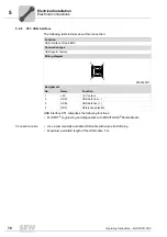
5.9.3
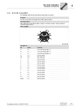
X8: AC 400 V output and CAN bus (DSC hybrid)
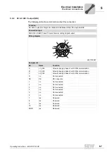
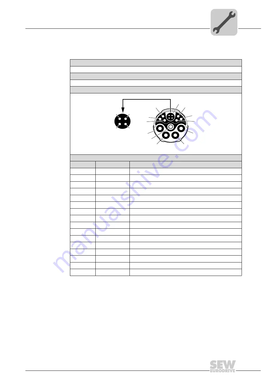
The following table shows information about this connection:
Function
AC 400 V output, CAN bus (SBus)
Connection type
M23 H-Tec, SEW P insert 15-pole, female, coding ring red-violet
Wiring diagram
2749367179
Assignment
No.
Name
Function
A
L1
Actuator supply phase L1
B
L2
Actuator supply phase L2
C
L3
Actuator supply phase L3
D
n.c.
Not connected
PE
PE
PE connection
1
n.c.
Not connected
2
n.c.
Not connected
3
n.c.
Not connected
4
n.c.
Not connected
5
n.c.
Not connected
6
n.c.
Not connected
7
CAN_L
CAN data line (low)
8
CAN_GND
Reference potential CAN bus
9
CAN_H
CAN data line (high)
10
n.c.
Not connected
SHLD
CAN_SHLD
Shield/equipotential bonding CAN bus
A
6
4
5
PE
B
C
D
SHLD
1
2
3
8
7
9
10
Summary of Contents for MOVIFIT FDC
Page 2: ...SEW EURODRIVE Driving the world...
Page 137: ...Operating Instructions MOVIFIT FDC 137 Index Y Y adapter 77 0 9 24 V terminals connection 55...
Page 138: ......
Page 139: ......


