84
Operating Instructions – MOVIFIT® FDC
5
Connection examples
Electrical Installation
5.12 Connection examples
5.12.1 Connecting external SBus
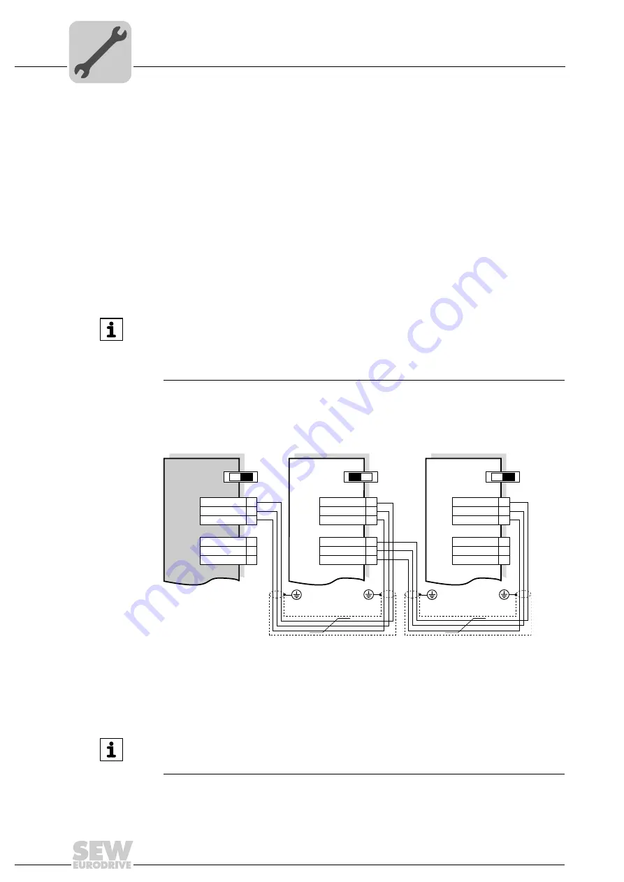
The following figures show the connection of BSus slave units to MOVIFIT
®
FDC:
• If the MOVIFIT
®
unit is located at the end of an SBus segment, it is only connected
via the incoming SBus cable (CAN).
• To prevent malfunctions in the bus system due to reflections, etc., the SBus segment
must be terminated using bus terminating resistors at the first and last physical sta-
tions.
• The bus terminating resistors are already installed in the MOVIFIT
®
ABOX and can
be activated using switch S3.
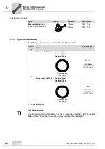
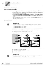
Connection example 1:
The SBus master MOVIFIT
®
FDC is located at the end of the SBus segment.
DIP switch S3 of the SBus master MOVIFIT
®
FDC = "ON".
INFORMATION
Connection example 1 applies in combination with the following master ABOXes:
• Standard ABOX "MTA...-S04.-...-00"
• Hybrid ABOX "MTA...-S54.-...-00"
• Hybrid-ABOX "MTA...-S64.-...-00"
4273650443
X = 16
−
Number of connected SNI units
[1] DIP switch S3 for bus termination
[2] DIP switch for bus termination in the slave unit
[3] EMC cable gland
[3]
[3]
SBus-SLAVE 1
SBus-SLAVE X
–
X25
S.
X25
S.
[2]
[2]
MOVIFIT®-FDC
X25
10
9
23
39
38
53
SBus (CAN)
IN
OUT
IN
OUT
S3
[1]
[3]
[3]
SBus (CAN)
ON
ON
OFF
CAN_GND
CAN_GND
CAN_L
CAN_H
CAN_L
CAN_H
CAN_GND
CAN_GND
CAN_L
CAN_H
CAN_L
CAN_H
CAN_GND
CAN_GND
CAN_L
CAN_H
CAN_L
CAN_H
INFORMATION
If the SBus is connected to the master using the external plug connector X14, then
only connection example 1 is possible.
Summary of Contents for MOVIFIT FDC
Page 2: ...SEW EURODRIVE Driving the world...
Page 137: ...Operating Instructions MOVIFIT FDC 137 Index Y Y adapter 77 0 9 24 V terminals connection 55...
Page 138: ......
Page 139: ......

