92
Operating Instructions – MOVIFIT® FDC
6
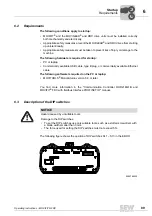
PC/laptop connection
Startup
6.5
PC/laptop connection
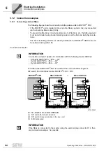
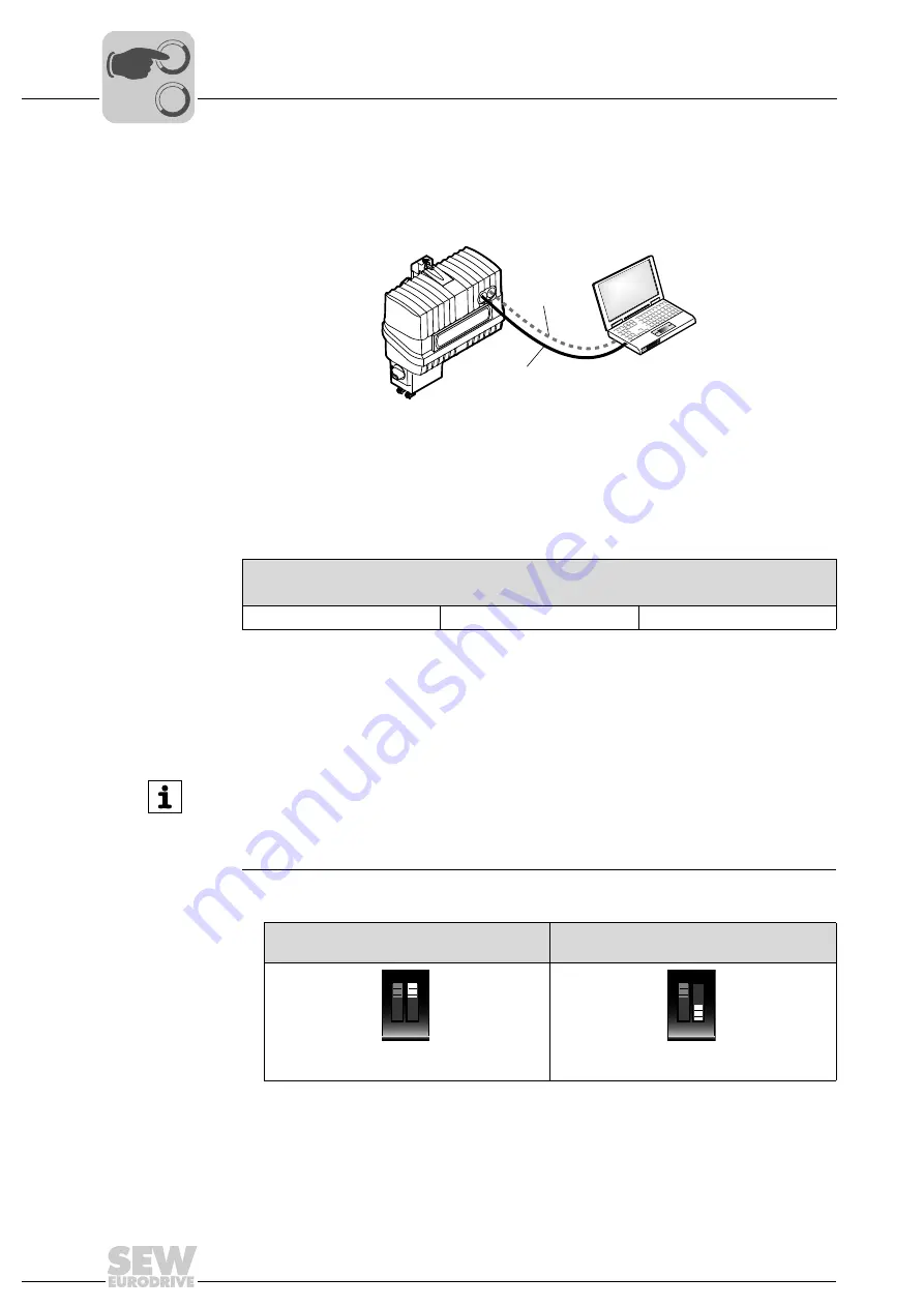
The following figure shows the connection between a PC/laptop and the engineering
interface of MOVIFIT
®
FDC:
The following table shows the IP address, the subnet mask, and the standard gateway
of the engineering interface of MOVIFIT
®
FDC:
6.6
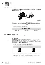
Startup of MOVIFIT
®
FDC
1. Check the connection of MOVIFIT
®
FDC.
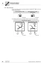
2. Select the communication protocol using DIP switch S12/2.
3. Place the MOVIFIT
®
EBOX onto the ABOX and close it.
4. Switch on the 24 V supply voltage. The "24V_C" LED should now light up green.
3041009931
[1] Commercially available Ethernet cable
You have to configure the Ethernet interface to a
fixed IP address.
[2] Commercially available USB cable, type B The USB interface configures itself automati-
cally.
Ethernet service interface
Standard IP address
Subnet mask
Standard gateway
192.168.10.4
255.255.255.0
192.168.10.1
[2]
[1]
INFORMATION
With PROFINET IO, EtherNet/IP or Modbus/TCP, you do not have to make any set-
tings on MOVIFIT
®
FDC. The entire startup is carried out using software tools. For a
description, refer to the "Communication Controller DHR21B/41B and MOVIFIT
®
FDC
with PROFINET IO Fieldbus Interface" manual:
PROFINET IO
DIP switch S12/2 = ON
EtherNet/IP or Modbus/TCP
DIP switch S12/2 = OFF
9007202400256779
9007202400668171
S12
ON
1 2
S12
ON
1 2
00
I
Summary of Contents for MOVIFIT FDC
Page 2: ...SEW EURODRIVE Driving the world...
Page 137: ...Operating Instructions MOVIFIT FDC 137 Index Y Y adapter 77 0 9 24 V terminals connection 55...
Page 138: ......
Page 139: ......

