7
Operation
MOVIFIT® MC status LEDs
Operating Instructions – MOVIFIT
®
MC
130
7.1.3
Bus-specific LEDs for DeviceNet™
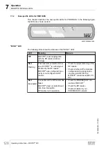
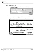
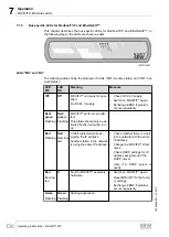
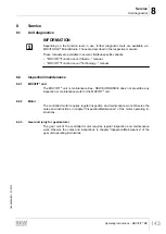
This chapter describes the bus-specific LEDs for DeviceNet™. In the following figure,
the LEDs are shown as dark:
DI03
DI01 DI02
DI00
DI04 DI05 DI06 DI07
DI08 DI09 DI10 DI1
1
DI12/DO00
DI13/DO01
DI14/DO02
DI15/DO03
®
MOVIFIT
SF/USR
BUS-F
ST
O
24V
-C
24V
-S
MOD/Net
PIO BIO
9007200284656779
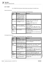
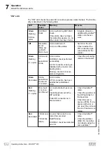
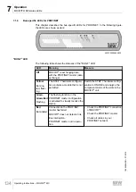
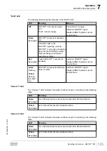
"BUS-F" LED
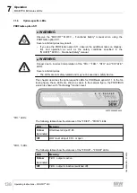
The "BUS-F" LED indicates the physical state of the bus node. The functionality is de-
scribed in the following table:
LED
Possible
cause
Meaning
Measure
Off
No error
The number of bus errors is with-
in the normal range (error active
state).
-
Red
Flashing
(1 s cycle)
Bus
warning
The unit is performing a DUP-
MAC check and cannot send any
messages because no other sta-
tions are connected to the bus
(error passive state).
• Integrate another
DeviceNet™ station
into the network.
• Check the wiring and
terminating resistors.
Red
Illuminated
Bus error Bus off status.
The number of physical bus er-
rors has increased despite
switchover to error-passive state.
Access to the bus is switched off.
• Check the setting for
the address baud rate,
wiring, and terminating
resistors.
Yellow
Illuminated
Power off External voltage supply has
been turned off or is not connec-
ted.
• Check the external
voltage supply and
wiring of the unit.
19484828/EN – 01/2015

