7
Operation
MOVIFIT® MC status LEDs
Operating Instructions – MOVIFIT
®
MC
134
7.1.4
Bus-specific LEDs for PROFINET
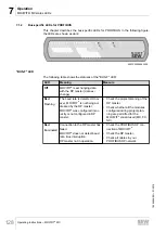
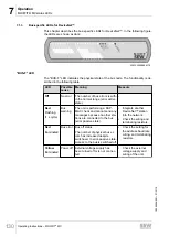
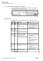
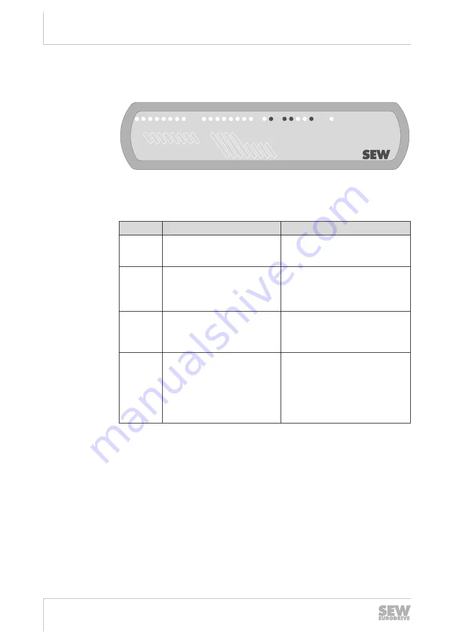
This chapter describes the bus-specific LEDs for PROFINET. In the following figure,
the LEDs are shown as dark:
DI03
DI01 DI02
DI00
DI04 DI05 DI06 DI07
DI08 DI09 DI10 DI1
1
DI12/DO00
DI13/DO01
DI14/DO02
DI15/DO03
®
MOVIFIT
SF/USR
BUS-F
RUN
ST
O
24V
-C
24V
-S
link/act1
link/act2
9007200284650635
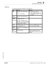
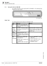
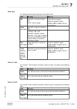
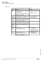
"BUS-F" LED
The following table shows the statuses of the "BUS-F" LED:
LED
Meaning
Measure
Off
MOVIFIT
®
is exchanging data
with the PROFINET master (data
exchange).
-
Yellow
Illumina-
ted, flash-
ing
The STEP 7 hardware configura-
tion contains a module that is not
permitted.
Switch the STEP 7 hardware config-
uration to ONLINE and analyze the
component status of the slots in the
MOVIFIT
®
unit.
Green,
Green/Red
Flashing
The flashing function in the
PROFINET master configuration
is activated to visually localize the
station.
-
Red
Illuminated
Connection to the PROFINET
master has failed.
MOVIFIT
®
does not detect a link.
Bus interruption.
PROFINET master not in opera-
tion.
• Check the PROFINET connection
of MOVIFIT
®
.
• Check the PROFINET master.
• Check all cables in your
PROFINET network.
19484828/EN – 01/2015

