3
Unit structure
ABOX (passive connection unit)
Operating Instructions – MOVIFIT
®
MC
16
3.4
ABOX (passive connection unit)
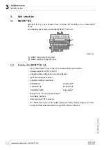
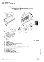
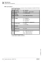
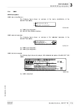
The following figure provides an example of the MOVIFIT
®
ABOX:
X
ABOX "MTA...-...-00"
X
[13]
[1]
[2]
[3]
[4]
[5]
ON
1
2
3
4
5
6
7
8
S2
S1
[6]
[8]
[9]
[10]
[11]
[12]
[7]
S3
I
ON
0 OFF
9007200272383883
[1]
Mounting rail
[2]
Connection to EBOX
[3]
Nameplate of the complete unit (EBOX and ABOX)
[4]
Internal nameplate of the ABOX
[5]
Protection cover
[6]
DIP switch S2 for bus address (PROFIBUS and DeviceNet™ design only)
[7]
DIP switch S3 for SBus bus termination
[8]
DIP switch S1 for bus termination (PROFIBUS design only)
[9]
Maintenance switch (triple lock)
[10] Grounding screws
[11] ABOX device identification
[12] External nameplate of the ABOX
[13] Diagnostic interface below screw fitting
19484828/EN – 01/2015


