4
Mechanical installation
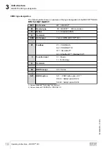
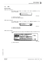
Installation
Operating Instructions – MOVIFIT
®
MC
27
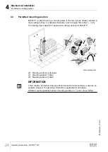
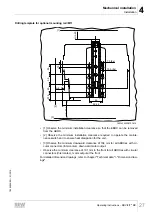
Drilling template for optional mounting rail /M11
334.4
66
min. 40
min. 50
[1]
[2]
15
37.5
40
50
50
7.0 (8x)
13.9 (8x)
[3]
min. 104
18014399308791819
• [1] Observe the minimum installation clearance so that the EBOX can be removed
from the ABOX.
• [2] Observe the minimum installation clearance required to operate the mainte-
nance switch and to ensure heat dissipation for the unit.
• [3] Observe the minimum downward clearance of 104 mm for all ABOXes with cir-
cular connectors (Intercontec), downward motor output.
• Observe the minimum clearance of 191 mm to the front for all ABOXes with circular
connectors (Intercontec), motor output at the front.
For detailed dimension drawings, refer to chapter "Technical data" > "Dimension draw-
ings".
19484828/EN – 01/2015

