5
Electrical installation
Installation instructions (all versions)
Operating Instructions – MOVIFIT
®
MC
40
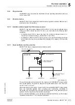
24V_S = Actuator supply
The 24V_S voltage level supplies:
• The digital outputs DO..
• The connected actuators
• The VO24_IV sensor supply output
The digital inputs DI12 – DI15 are connected to the reference potential 0V24_S as
these can be connected to the same connections as an alternative to the outputs.
To centrally deactivate the actuators of the plant, you can disconnect the 24V_S volt-
age level during operation, if required.
24V_P = Inverter supply
The 24V_P voltage level supplies the connected MOVIMOT
®
inverter with 24 V. The
voltage is conveyed through the EBOX, where it supplies the RS485 interfaces of the
MOVIMOT
®
inverters.
Depending on the application, the 24V_P voltage level can be supplied by 24V_C or
24V_S (via jumpers at X29) or externally. The required jumpers are included in the de-
livery.
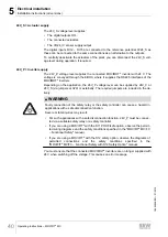
WARNING
Faulty connection of the safety relay or the safety controller can cause a hazard in
applications with a safe disconnection function.
Severe or fatal injuries may result.
• For such applications with a safe disconnection function, 24V_P must be connec-
ted via a suitable safety relay or a safety controller.
• If you are using a MOVIFIT
®
with the S11 PROFIsafe option, observe the permit-
ted wiring diagrams and the safety conditions specified in the "MOVIFIT
®
MC/FC
– Functional Safety" manual.
• If you are using a MOVIFIT
®
with the S12 safety option, observe the diagrams of
permitted connections and the safety conditions specified in the
"MOVIFIT
®
MC/FC – Functional Safety with S12 Safety Option" manual.
You must ensure that the connected MOVIMOT
®
inverters are no longer supplied with
24 V when switching off the voltage. This causes an error message.
19484828/EN – 01/2015


