5
Electrical installation
Installation instructions (all versions)
Operating Instructions – MOVIFIT
®
MC
44
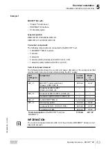
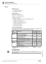
Example 2
MOVIFIT
®
MC with:
• "Technology" function level
• EtherNet/IP™ interface
Type designation
EBOX: MTM11A000-E31A-00
ABOX: MTA11A-503-S513-M01-00
Connected components
The following components are connected to the MOVIFIT
®
unit:
• 2 MOVIMOT
®
MM..D inverters
• 8 sensors, each with 50 mA (1.2 W)
• 2 actuators, each with 100 mA (2.4 W)
• 0 sensors (safety related)
• 0 actuators (safety related)
Current and power demand
The following table shows the current and power demands of the components that
must be taken into account when dimensioning the 24 V supply:
24 V
voltage lev-
el
Component
Current
consump-
tion
Power
at
V
IN
= 24 V
24V_C
MOVIFIT
®
control electronics
"Technology" EtherNet/IP™
250 mA
6.0 W
8 sensors at DI00 to DI11
(VO24_I to VO24_III)
400 mA
9.6 W
24V_S
0 sensors at DI12 to DI15.. (VO24_IV)
–
–
2 actuators at DO00, DO01 (VO24_IV)
200 mA
4.8 W
24V_P
2 x MOVIMOT
®
MM..D
2 x 120 mA
2 x 2.9 W
24V_O
0 options
–
–
0 sensors at F-DI..
–
–
0 actuators at F-DO..
–
–
Total consumption
of the MOVIFIT
®
unit (incl.
MOVIMOT
®
):
1090 mA
26.2 W
INFORMATION
The current and power demands (400 V) of the connected MOVIMOT
®
drives are not
taken into account.
19484828/EN – 01/2015

