5
Electrical installation
Standard ABOX "MTA...-S01.-...-00"
Operating Instructions – MOVIFIT
®
MC
54
5.5.4
Terminal positions
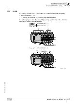
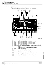
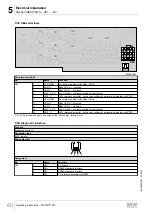
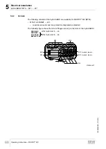
The following figure shows the position of the terminals in the ABOX:
1
2
3
4
5
6
16
15
14
13
12
11
1
2 3 4 5 6
7
8
18
17
16
15
14
13
12
11
1
2
3
4
14
13
12
11
[3]
X8
[4]
X71
[5]
X81
[6]
X29
[1]
X1
[13]
X91
[14]
X9
[12]
X20
[11]
X45
[10]
X25
[8] X35
[7] X30 (X31)
[9] X50
1
2
3 4
5
1
2
3 4
5
1
2
3 4
5
1
2
3
4
1
2
3
4
1
2
3
4
[2]
X7
5774331915
[1]
X1
Supply system terminals
[2]
X7
Terminals for MOVIMOT
®
drive 1, phase L1 to L3
[3]
X8
Terminals for MOVIMOT
®
drive 2, phase L1 to L3
[4]
X71
Terminals for MOVIMOT
®
drive 1, 24 V + RS485
[5]
X81
Terminals for MOVIMOT
®
drive 2, 24 V + RS485
[6]
X29
24 V distributor terminals
[7]
X30, (X31) Fieldbus terminals or fieldbus plug connector, depending on field-
bus.
The area dependent on the fieldbus type is hatched.
[8]
X35
SBus terminals (CAN)
[9]
X50
Diagnostic interface (RJ10, female)
[10]
X25
I/O terminals for digital inputs/outputs
(connection of s actuators)
[11]
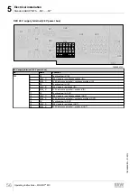
X45
I/O terminals for safety-related digital inputs/outputs
(only with option card S11, S12A or S12B)
[12]
X20
24 V supply terminal (24 V power bus)
[13]
X91
Terminals for MOVIMOT
®
drive 3, 24 V + RS485
[14]
X9
Terminals for MOVIMOT
®
drive 3, phase L1 to L3
19484828/EN – 01/2015

