5
Electrical installation
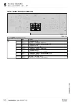
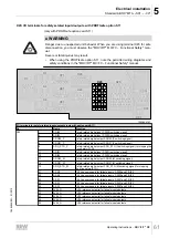
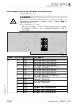
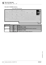
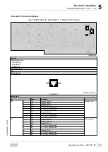
Standard ABOX "MTA...-S01.-...-00"
Operating Instructions – MOVIFIT
®
MC
55
5.5.5
Terminal assignment
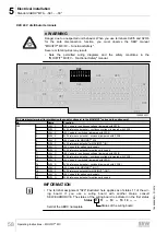
WARNING
Electric shock due to dangerous voltages in the ABOX.
The maintenance switch only disconnects the connected MOVIMOT
®
drives from the
supply system. Voltage is still present in the X1 terminals of the MOVIFIT
®
unit. Volt-
age is still present in the X7, X8, and X9 terminals for up to 1 minute after the main-
tenance switch is activated.
• Switch off the power to the MOVIFIT
®
unit using a suitable external disconnecting
device, and wait at least 1 minute before opening the wiring space.
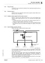
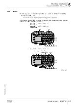
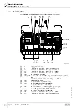
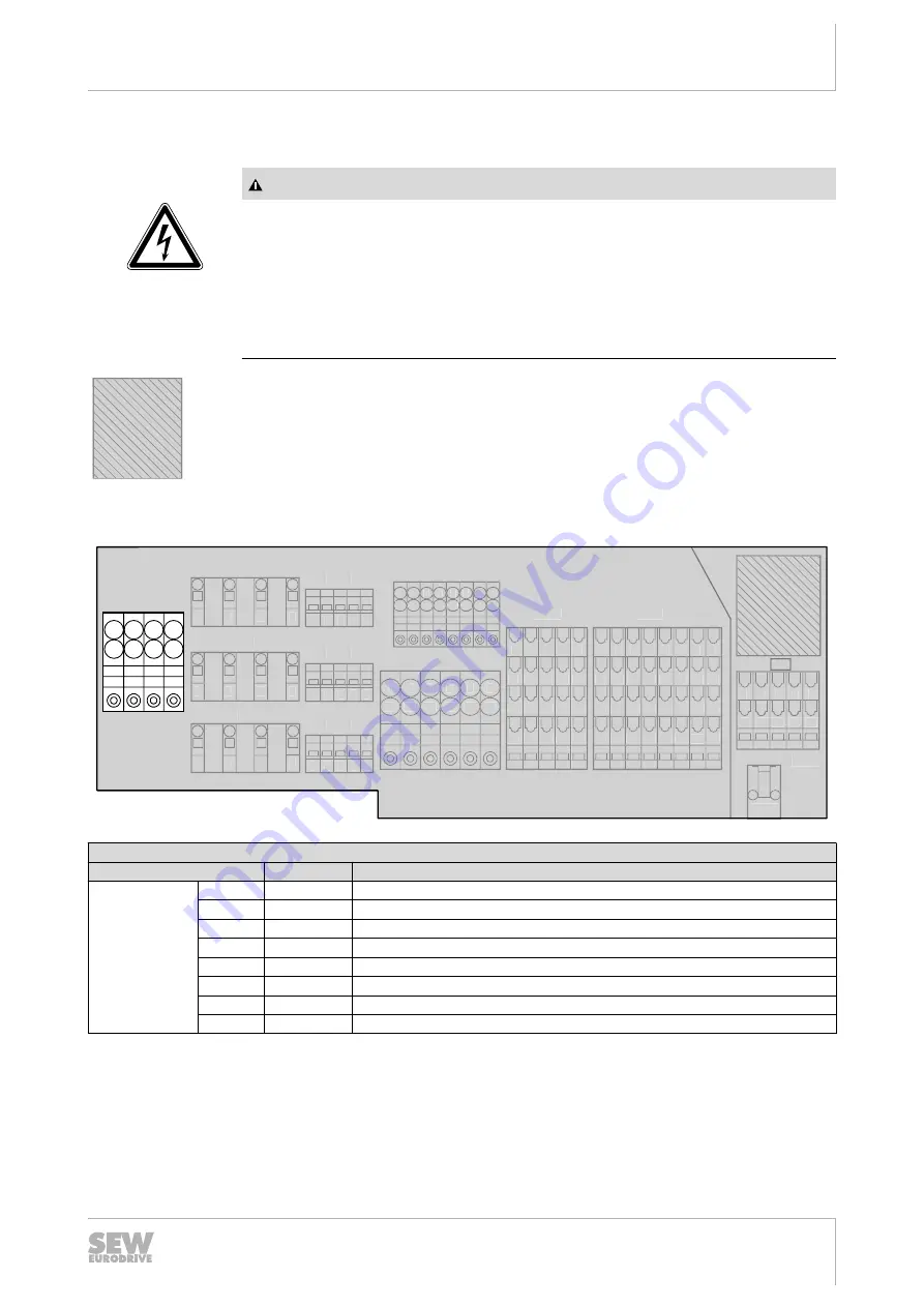
The terminal diagrams depicted in this chapter differ depending on the fieldbus sys-
tem used. The area dependent on the fieldbus is therefore depicted as hatched and is
described in the following chapters.
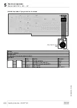
X1: Line terminals (power bus)
1
11
11 12
12 13
13 14
1415
15 16
16
2 3 4 5 6
17
1718
18
7 8
X29
S3
1 2 3 4 5
1
2
3
4
1
2
3
4
X71
X20
X45
X25
X35
1 2 3 4 5
X81
X50
11
1 2 3 4 5 6 7 8
12 13 14 15 16 17 18
31 32 33 34 35 36 37 38
21 22 23 24 25 26 27 28
11
1 2 3 4 5
12 13 14 15
31 32 33 34 35
21 22 23 24 25
1
11 12 13 14 15 16
2
3
4
5
6
11
1 2 3 4 5
12 13 14 15
1 2 3 4 5
X91
X7
1
2
3
4
X8
X9
1
2
3
4
11 12 13 14
X1
1019979147
Line terminal (power bus)
No.
Name
Function
X1
1
PE
Line connection PE (IN)
2
L1
Line connection phase L1 (IN)
3
L2
Line connection phase L2 (IN)
4
L3
Line connection phase L3 (IN)
11
PE
Line connection PE (OUT)
12
L1
Line connection phase L1 (OUT)
13
L2
Line connection phase L2 (OUT)
14
L3
Line connection phase L3 (OUT)
19484828/EN – 01/2015

