5
Electrical installation
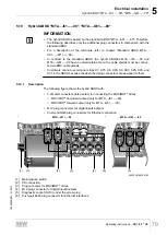
Hybrid ABOX "MTA...-I51.-...-00", "MTA...-G51.-...-00"
Operating Instructions – MOVIFIT
®
MC
78
5.9.3
Plug connector positions
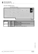
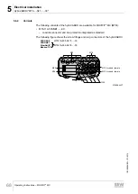
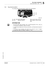
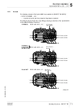
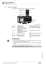
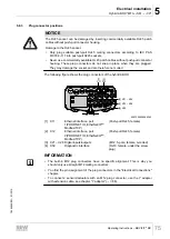
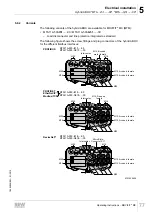
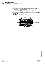
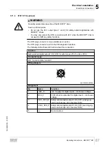
The following figure shows the plug connectors of the hybrid ABOX:
DeviceNet™:
[9] X21 – X24
[9] X25 – X28
[10] X50
[2] X12
[4] X12
[1] X11
[3] X11
PROFIBUS:
Ethernet:
[5] X11
MTA11A-503-G
51.
-...-00:
MTA11A-503-I
51.
-...-00:
[6] X75
[6] X75
X95 [8]
X95 [8]
X85 [7]
X85 [7]
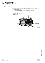
5798129803
[1]
X11
PROFIBUS input
(M12, 5-pole, male, B-coded)
[2]
X12
PROFIBUS output
(M12, 5-pole, female, B-coded)
[3]
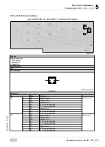
X11
Ethernet interface, port 1
(PROFINET, EtherNet/IP™,
Modbus/TCP)
(M12, 4-pole, female, D-coded)
[4]
X12
Ethernet interface, port 2
(PROFINET, EtherNet/IP™,
Modbus/TCP)
(M12, 4-pole, female, D-coded)
[5]
X11
DeviceNet™ interface
(micro-style connector, male, A-
coded)
[6]
X75
Connection for MOVIMOT
®
drive 1
(Intercontec 723 H-Tec,
7 + 3
‑
pole, female, code 3)
[7]
X85
Connection for MOVIMOT
®
drive 2
[8]
X95
Connection for MOVIMOT
®
drive 3
[9]
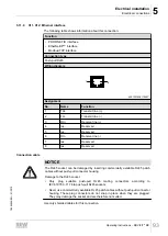
X21 – X28 Digital inputs/outputs
(M12, 5-pole, female, A-coded)
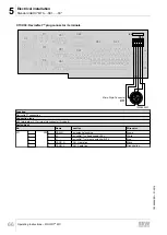
[10] X50
Diagnostic interface
(RJ10, female, under the screw
plug)
INFORMATION
• The built-in M12 plug connectors have no specific alignment. This is why you
should only use straight M12 mating connectors.
• You find the pin assignment of the plug connectors in the "Electrical Connections"
chapter.
• To connect 2 sensors/actuators to an M12 plug connector, use the Y adapter with
an extension cable; see the chapter "Y adapter" (
19484828/EN – 01/2015

