5
Electrical installation
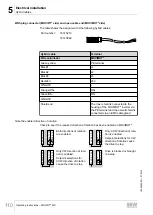
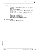
Power bus connection examples
Operating Instructions – MOVIFIT
®
MC
97
5.13
Power bus connection examples
5.13.1
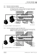
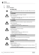
Connection example with a common 24 V voltage circuit
The following figure shows a connection example for the power bus with a common
24 V voltage circuit for the sensor/actuator supply. In the example, the MOVIMOT
®
inverters are supplied by the 24V_C voltage:
1
2
3
4
5
6
11
12
13
14
15
16
1
2
3
4 11 12 13 14
PE
L1
L2
L3
PE
L1
L2
L3
L3
L2
L1
PE
L3
L2
L1
PE
X1
1
2
3
4
5
6
7
8
X29
11 12 13 14 15 16 17 18
X20
[1]
MOVIFIT
®
-MC
FE
+24V
0V24V
FE
+24V
0V24V
11
12
13
14
15
16
18
17
5
1
2
1
3
4
6
7
8
X1
X29
X20
9007200277426827
[1]
Example for MOVIMOT
®
inverters supplied by 24V_C
5.13.2
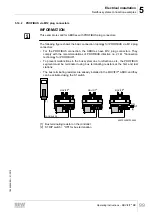
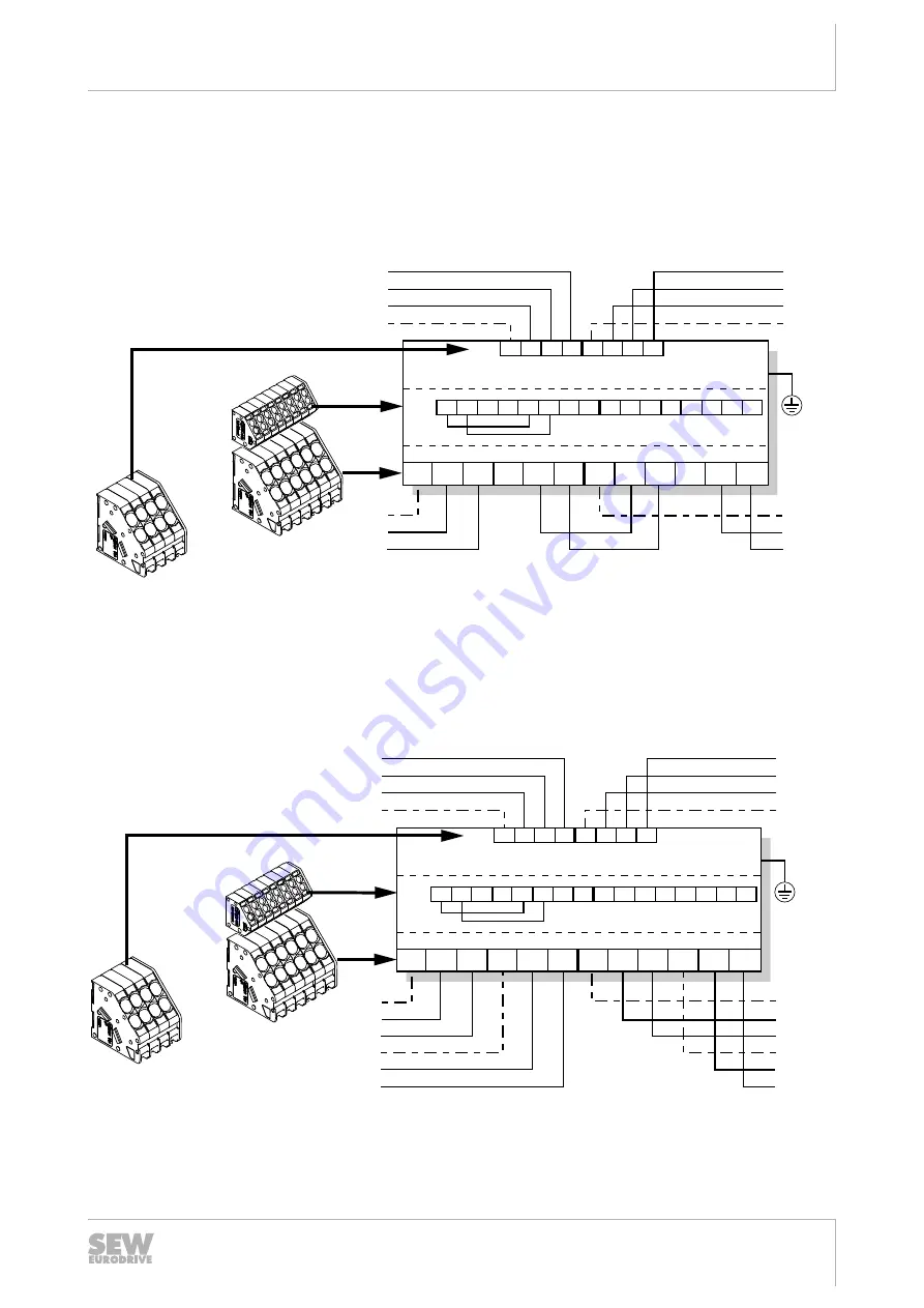
Connection example with two separate 24 V voltage circuits
The following figure depicts a basic connection example for the power bus with two
separate 24 V voltage circuits for sensor/actuator supply. In the example, the
MOVIMOT
®
inverters are supplied by the 24V_C voltage:
1
2
3
4
5
6
11
12
13
14
15
16
1
2
3
4 11 12 13 14
PE
L1
L2
L3
PE
L1
L2
L3
L3
L2
L1
PE
L3
L2
L1
PE
0V24V_C
FE
+24V_C
0V24V_C
+24V_S
0V24V_S
FE
X1
1
2
3
4
5
6
7
8
11 12 13 14
15 16 17 18
X29
X20
[1]
MOVIFIT
®
-MC
11
12
13
14
15
16
18
17
5
1
2
1
3
4
6
7
8
X1
X29
X20
FE
+24V_C
+24V_S
0V24V_S
FE
9007200277432971
[1]
Example for MOVIMOT
®
inverters supplied by 24V_C
19484828/EN – 01/2015


