6
Startup
Startup of MOVIFIT® on the fieldbus
Operating Instructions – MOVIFIT
®
MC
121
6.6
Startup of MOVIFIT
®
on the fieldbus
Startup of
MOVIFIT®
on the
fieldbus
INFORMATION
The entire fieldbus startup is carried out via software tools and is described in the re-
spective manuals:
The "MOVIFIT
®
Function Level Classic" and "MOVIFIT
®
Function Level Technology"
manuals are available in several fieldbus-specific designs.
• "MOVIFIT
®
Function Level Classic..." manual
• "MOVIFIT
®
Function Level "Technology..." manual
6.6.1
Startup in conjunction with PROFIBUS
1. Check the MOVIFIT
®
connection.
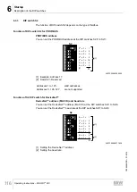
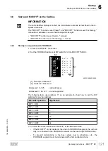
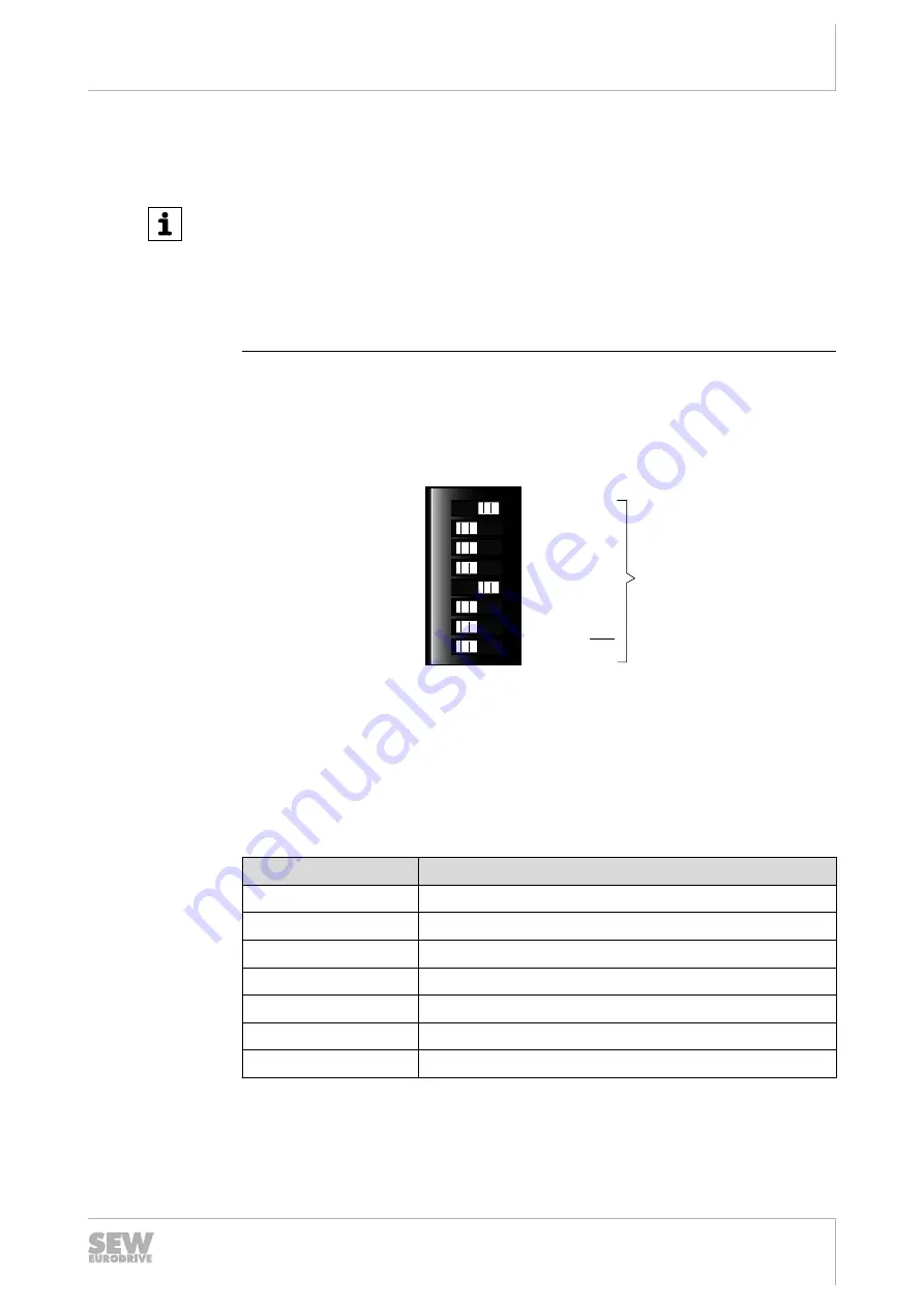
2. Set the PROFIBUS address at DIP switch S2 of the MOVIFIT
®
ABOX.
S2
2
0
x 1 = 1
2
1
x 0 = 0
2
2
x 0 = 0
2
3
x 0 = 0
2
5
x 0 = 0
2
6
x 0 = 0
2
4
x 1 = 16
17
[2]
[1]
ON
1
2
3
4
5
6
7
8
9007200092252555
[1] Example: Address 17
[2] Switch 8 = Reserved
Addresses 1 to 125:
valid addresses
Addresses 0, 126, 127: are not supported
The following table uses address 17 as an example to show how to set the DIP
switches for any bus address:
DIP switch position
Significance
DIP 1 = ON
1
DIP 2 = OFF
2
DIP 3 = OFF
4
DIP 4 = OFF
8
DIP 5 = ON
16
DIP 6 = OFF
32
DIP 7 = OFF
64
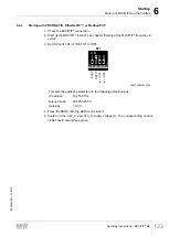
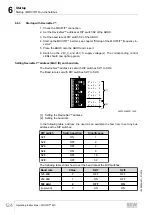
3. Connect the bus termination on MOVIFIT
®
at the last bus station.
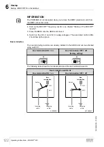
• If the MOVIFIT
®
unit is located at the end of a PROFIBUS segment, the unit can
only be connected to the PROFIBUS network via the incoming PROFIBUS line.
• To prevent malfunctions in the bus system due to reflections, etc., the
PROFIBUS segment must be terminated at the first and last stations.
19484828/EN – 01/2015

