7
Operation
MOVIFIT® MC status LEDs
Operating Instructions – MOVIFIT
®
MC
125
7
Operation
7.1
MOVIFIT
®
MC status LEDs
MOVIFIT®
MC status
LEDs
7.1.1
General LEDs
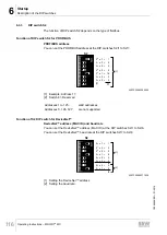
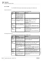
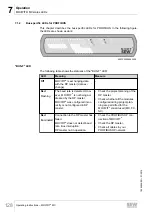
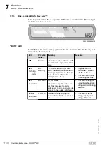
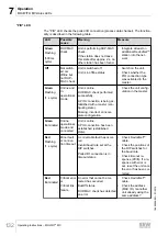
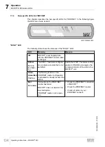
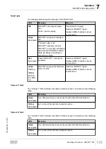
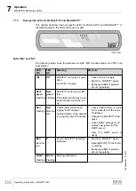
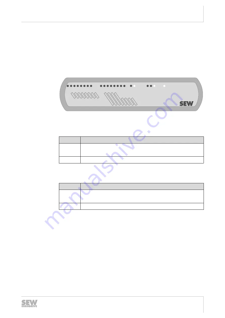
This chapter describes the fieldbus-independent and option-independent LEDs. These
LEDs are shown as dark in the figures. The LEDs that are shown in white differ de-
pending on which fieldbus version is used. They are described in the following chap-
ters. The following figure depicts examples of the PROFIBUS variants:
DI03
DI01DI02
DI00
DI04DI05DI06DI07
DI08DI09DI10DI1
1
DI12/DO00
DI13/DO01
DI14/DO02
DI15/DO03
®
MOVIFIT
SF/USR
BUS-F
RUN
ST
O
24V
-C
24V
-S
9007200284574091
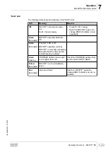
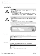
"DI.." LEDs
The following table shows the statuses of the "DI00 – DI15" LEDs:
LED
Meaning
Yellow
Illuminated
Input signal present at digital input DI..
Off
Input signal at digital input DI.. open or "0".
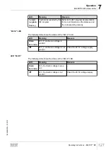
"DO.." LEDs
The following table shows the statuses of the "DO00 – DO03" LEDs.
LED
Meaning
Yellow
Illuminated
DO.. output switched.
Off
DO.. output logical "0".
19484828/EN – 01/2015

