4
Mechanical installation
Installation
Operating Instructions – MOVIFIT
®
MC
25
4.4
Installation
4.4.1
Mounting rail
MOVIFIT
®
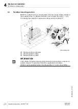
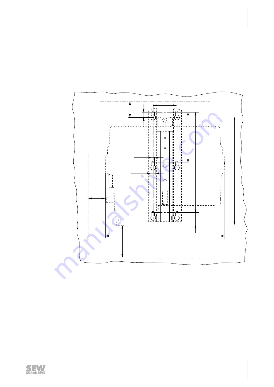
is equipped with a mounting rail to attach the unit to a level, low-vibration
mounting surface using M6 screws. For bore dimensions of the respective type of fix-
ture, see the following figures.
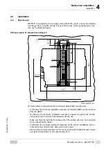
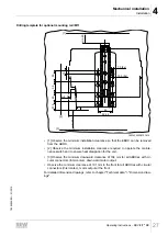
Drilling template for standard mounting rail
66
334.5
304.1
280
140
37,5
min. 40
15
min. 50
[1]
[2]
7.0 (6x)
13.9 (6x)
[3]
min. 104
27021598522763275
The hole pattern is also valid for the corrosion-resistant M2A mounting rail.
• [1] Observe the minimum installation clearance so that the EBOX can be removed
from the ABOX.
• [2] Observe the minimum installation clearance required to operate the mainte-
nance switch and to ensure heat dissipation for the unit.
• Make sure that the permitted bending radii of the cables used are not exceeded
when connecting the cables.
• [3] Observe the minimum downward clearance of 104 mm for all ABOXes with cir-
cular connectors (Intercontec), downward motor output.
• Observe the minimum clearance of 191 mm to the front for all ABOXes with circular
connectors (Intercontec), motor output at the front.
19484828/EN – 01/2015

