5
Electrical installation
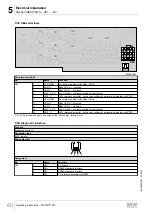
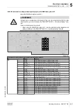
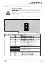
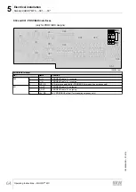
Standard ABOX "MTA...-S01.-...-00"
Operating Instructions – MOVIFIT
®
MC
50
5.5.3
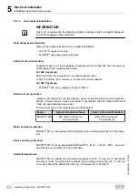
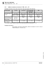
Additional installation instructions for "MTA...-S01.-...-00"
Permitted connection cross section and current carrying capacity of the terminals
Terminal data
X1, X20
X7, X8, X9
X25, X30, X31,
X35, X45, X71,
X81, X91
X29
Connection cross
section
0.2 – 6 mm
2
0.08 – 4
1)
mm
2
0.08 – 2.5
1)
mm
2
0.2 – 1.5
1)
mm
2
AWG 24 – AWG 10
AWG 28 –
AWG 12
1)
AWG 28 –
AWG 14
1)
AWG 24 –
AWG 16
1)
Current carrying ca-
pacity (max. contin-
uous current)
X1: 32 A
X20: 16 A
20 A
10 A
10 A
Length of conductor
to be stripped
13 – 15 mm
8 – 9 mm
5 – 6 mm
9 – 10 mm
1) The maximum permitted cross section is reduced by one unit when using conductor end sleeves (e.g. 2.5 → 1.5)
Conductor end sleeves
Use conductor end sleeves without plastic collars for terminals X1, X20, X7, X8 and
X9 (DIN 46228 part 1, material E-CU).
19484828/EN – 01/2015

