5
Electrical installation
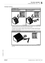
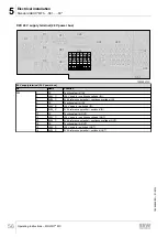
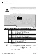
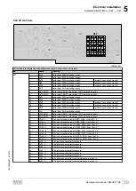
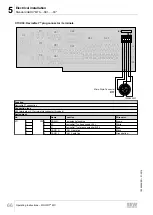
Standard ABOX "MTA...-S01.-...-00"
Operating Instructions – MOVIFIT
®
MC
60
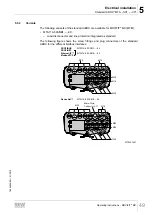
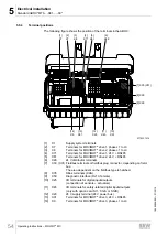
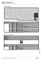
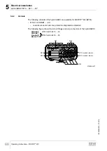
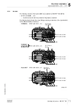
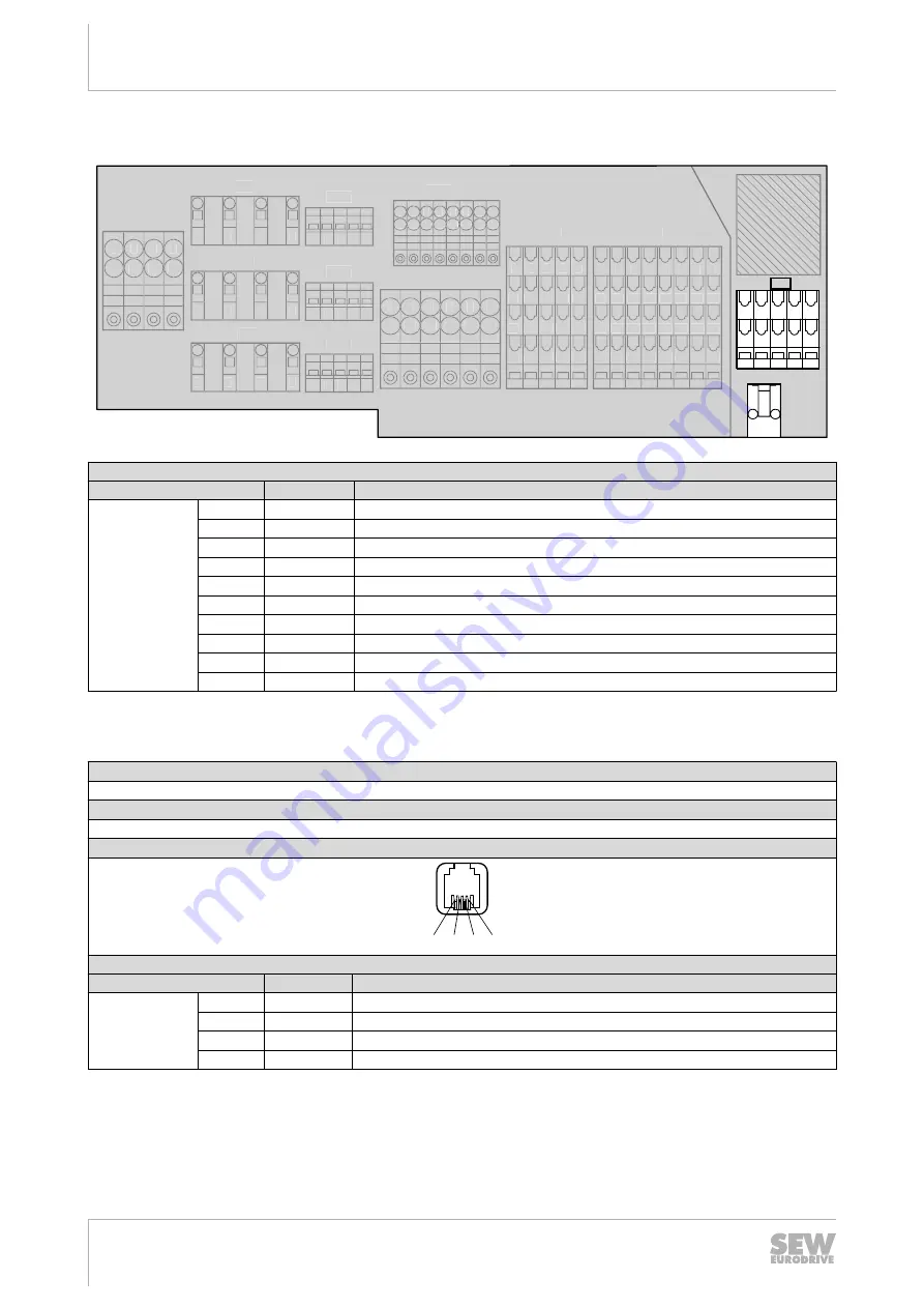
X35: SBus terminals
1
11
11 12
12 13
13 14
1415
15 16
16
2 3 4 5 6
17
1718
18
7 8
X29
11
1 2 3 4 5 6 7 8
12 13 14 15 16 17 18
31 32 33 34 35 36 37 38
21 22 23 24 25 26 27 28
X25
1
11 12 13 14 15 16
2
3
4
5
6
1
2
3
4
11 12 13 14
X1
1
1 2 3 4 5
2
3
4
1
2
3
4
X20
X71
X45
1 2 3 4 5
X81
11
1 2 3 4 5
12 13 14 15
31 32 33 34 35
21 22 23 24 25
1 2 3 4 5
X91
X7
1
2
3
4
X8
X9
S3
11
1 2 3 4 5
12 13 14 15
X35
X50
1020542987
SBus terminal (CAN)
No.
Name
Function
X35
1)
1
CAN_GND
0 V reference potential for SBus (CAN)
2
CAN_H
SBus CAN_H – incoming
3
CAN_L
SBus CAN_L – incoming
4
+24V_C_PS
+24 V supply – continuous voltage for peripheral
5
0V24_C
0V24 reference potential – continuous voltage for peripheral (jumpered with X20/3)
11
CAN_GND
0 V reference potential for SBus (CAN)
12
CAN_H
SBus CAN_H – outgoing
13
CAN_L
SBus CAN_L – outgoing
14
+24V_C_PS
+24 V supply – continuous voltage for peripheral
15
0V24_C
0V24 reference potential – continuous voltage for peripheral (jumpered with X20/3)
1) The X35 terminals can only be used with the "Technology" function level.
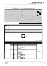
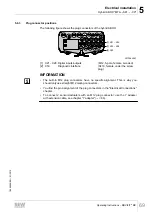
X50: Diagnostic interface
Function
Diagnostic interface
Connection type
RJ10, female
Wiring diagram
1
2
3
4
Assignment
No.
Name
Function
X50
1
+5V
5 V supply
2
RS+
RS485 diagnostic interface
3
RS-
RS485 diagnostic interface
4
0V5
0 V reference potential for RS485
19484828/EN – 01/2015

