5
Electrical installation
Hybrid ABOX "MTA...-I51.-...-00", "MTA...-G51.-...-00"
Operating Instructions – MOVIFIT
®
MC
76
5.9
Hybrid ABOX "MTA...-I51.-...-00", "MTA...-G51.-...-00"
INFORMATION
• The hybrid ABOX is based on the standard ABOX "MTA...-S01.-...-00". Therefore,
the following describes only the additional plug connectors in comparison with the
standard ABOX.
• For a description of the terminals, refer to chapter "Standard ABOX MTA...-
• In contrast to the standard ABOX, the hybrid ABOXes MTA...-I51.-...-00 and
MTA...-G51.-...-00 have no shield plates. Here, the cable shields must be connec-
ted via EMC cable glands.
• Customers cannot use terminal strips X7, X71, X8, X81, X9, X91, X25, X30, and
X31 in the ABOX because the described plug connectors are assigned to them.
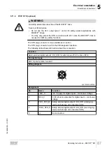
5.9.1
Description
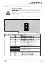
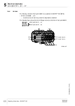
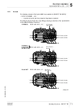
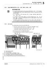
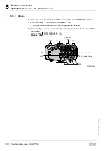
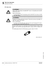
The following figure shows the hybrid ABOX with:
• 3 circular connectors (Intercontec) for connecting the MOVIMOT
®
drives
– MOVIMOT
®
downward output (only for MTA...-I51.-...-00)
– MOVIMOT
®
forward output (only for MTA...-G51.-...-00)
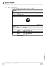
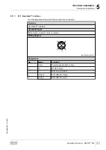
• M12 plug connectors for digital inputs/outputs
• M12 plug connectors for the fieldbus
[3]
X75
X95
X85
[2]
[1]
[4]
[3]
[5]
[6]
X21
X25
X26
X27
X28
X22
X11
X75
X95
X85
X12
X23
X24
MTA...-G51.-...-00
MTA...-I51.-...-00
9007204198798603
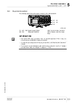
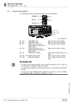
[1]
Maintenance switch
[2]
PE connection
[3]
Plug connector for MOVIMOT
®
drives
[4]
M12 plug connector for digital inputs/outputs
[5]
Diagnostic socket (RJ10) under the screw plug
[6]
M12 plug connector for the fieldbus connection
19484828/EN – 01/2015


