16
MOVITRAC
®
31.. – FRS 31
4
Parameters
P 764
Selection of mode
Value range 1...8
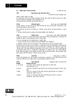
The selected mode determines how the slave reacts to a free-running signal.
“0” signal on terminal 102 or terminals 103-105, i.e. constant corrective control of synchronous
operation means counter value
∆α
= 0, i.e. no angular offset between master and slave.
In free-running mode (terminal 102 = “1”), the external setpoint n2 (terminals 34/35) or the inter-
nal setpoints n11/12/13 will be activ.
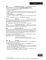
1) If the terminal has a signal of “1” for more than 3 seconds, the slave readjusts itself continuously 4 times per second.
Mode Mode of operation
Description
Command
Status
(P765)
slave
counter
LED
V12
(red)
Status
TL 102
Status TL
103-105
1
Free-running
– unrestricted
Slave counter (P 765) inactive /differential
counter inactive
“1”
Inactive
Inactive ON
2
Free-running
– limited perioddeter-
mined by term. 102
“1” signal initiates free-running.
When “1” signal removed, slave reduces the
angular difference to zero, i.e. synchronous oper-
ation in previous position relative to master
“1”
Inactive
Inactive ON
3
Free-running
– limited perioddeter-
mined by term. 102
– with new reference
point
“1” signal initiates free-running.
When “1” signal removed, slave goes to the
value of P 765. Slave thus has a new reference
point relative to the master
“1”
Inactive
active
ON
4
Free-running
- limited by value of
P 765
“1” signal (pulse duration > 100ms) initiates
start of limited free-running. Free-running ends
when value of P765 reached. Slave then
reduces the angular difference to zero, i.e.
synchronous operation in previous position
relative to master
“1”
Inactive
active
ON
5
Free-running
– limited by value of
(P 765)
– with new reference
point
“1” signal (pulse duration > 100 ms) initiates
start of limited free-running.Free-running ends
when value of P765 reached. Slave then
switches to synchronous operation with this
new value and thus has a new reference point
relative to the master.
The sign of P765 determines if the new refer-
ence point preceeds or follows the direction of
rotation, in respect to the new master position.
“1”
Inactive
active
ON
6
Synchronous operation
– with
intermittent
angular offset
Slave runs with offset (angular offset to master)
Value of P 766
“1”
TL. 103 =
“1”
Inactive ON
Slave runs with offset (angular offset to master)
Value of P 767
“1”
TL. 104 =
“1”
Slave runs with offset (angular offset to master)
Value of P 768
“1”
TL. 105 =
“1”
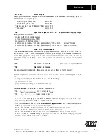
7
Synchronous operation
– with constant angular
offset (phase trim-
ming)
Slave runs with offset (angular offset to master)
Value of P 766
“1”
TL. 103 =
“1”
1)
Inactive ON
Slave runs with offset (angular offset to master)
Value of P 767
“1”
TL. 104 =
“1”
1)
Slave runs with offset (angular offset to master)
Value of P 768
“1”
TL. 105 =
“1”
1)
8
Free-running
– limited period deter-
mined by term. 102
– with new reference
point
“1” signal initiates Free-running.
Removal of the “1” signal sets the internal
counter for the angular offset to zero and a new
reference point is defined at the same time.
The value of P765 (slave - counter) is the new
reference point
“1”
Inactive
active
ON
Phone: 800.894.0412 - Fax: 888.723.4773 - Web: www.clrwtr.com - Email: info@clrwtr.com

