4
MOVITRAC
®
31.. – FRS 31
1
Introduction
1
Introduction
1.1
Description
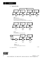
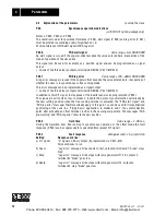
The synchronous operation function enables a group of asynchronous motors (master and slaves)
to maintain angular synchronism to one another or at a specified proportional ratio.
The synchronous operation function has 8 modes to cover a range of applications:
1) The value of P 765 can be modified from the menu using the “teach-in” procedure.
2) Continuous signal (t
≥
3 s) causes repeated angular offset with 4 angles per second
Modes
Functions
Application Examples
1
Free-running operation (for limited period) using
terminal 102 with slave counter (P 765) and differential
counter disabled.
Synchronous drives (conveyor belts, travel drives,
hoist drives on multi-column hoists).
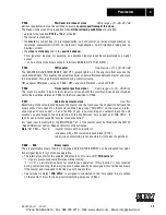
2
Free-running operation (for limited period) using
terminal 102. “1” signal on term. 102 initiates free-run-
ning, “0” signal on term. 102 initiates synchronous
operation; the angular difference between slave and
master, which occurred during free-running is reduced
to zero again, i.e. synchronous operation of slave with
previous position in relation to master.
Synchronous drives with intermittent offset;
free-running can be externally controlled in all
phases.
3
Free-running operation (for limited period) using
terminal 102. “1” signal on term. 102 initiates
free-running, “0” signal on term. 102 initiates synchro-
nous operation; slave receives new reference point in
relation to master (value of P 765
1)
).
Flying saws; free-running can be externally
controlled in all phases.
4
Free-running operation (limited by value of P 765).
“1” signal (pulse duration > 100 ms) initiates start of
restricted free-running operation. When the angular
difference between slave and master is the same as the
value of P 765, free-running terminates and the angular
difference is reduced to zero, i.e. synchronous
operation of slave with previous position in relation to
master.
As mode 2, though returns automatically to
synchronous operation.
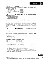
5
Free-running operation (limited by value of P 765
1)
).
“1” signal (pulse duration > 100 ms) initiates start of
restricted free-running operation. When the angular
difference between slave and master is the same as the
value of P 7651), free-running terminates automati-
cally. The angular difference is used as the new refer-
ence point of the slave to the master, i.e. synchronous
operation of slave with new reference point (value of P
765
1)
) in relation to master.
As mode 3, though returns automatically to
synchronous operation.
6
Synchronous operation with intermittent angular
offset; possible via terminals 103-105
2)
.
Creation of deliberate unbalance/ friction in
synchronized shafts
7
Synchronous operation with constant angular offset
(phase trimming); possible via terminals 103-105
2)
As mode 1, though with option of gradual position
adjustment.
8
Free-running operation (for limited period) using
terminal 102.
“1” signal on term. 102 initiates free-running
operation.
“0” signal on term. 102 initiates synchronous opera-
tion; the internal counter for the angular difference is
set to zero with the “1”
→
“0” edge and a new refer-
ence point is defined at the same time for synchronous
operation. The slave receives a value of P765 (slave
counter) as its new reference point.
Conveyor systems on which the goods to be
conveyed are fed onto and off the system at regular
intervals, e.g. docking roller conveyors.
Phone: 800.894.0412 - Fax: 888.723.4773 - Web: www.clrwtr.com - Email: info@clrwtr.com


