Movitrac
®
31.. – FRS 31
9
Commissioning
3
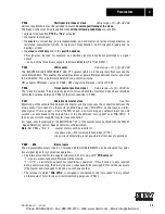
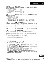
• If master and slave drives are to have the same direction of rotation:
CW rotation of master = CW rotation of slave
then the connection sequence of the motor phases and the units channels must be identical.
• If master and slave are to have opposite directions of rotation (e.g. output shafts of geared
motors with an even number of gear stages are opposite one another):
CW rotation of master = CCW rotation of slave
– Swap round setpoint channels from master to slave (swap terminals 98/99 and 100/101 on
slave in pairs).
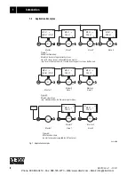
3.3
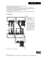
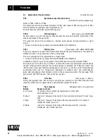
Wiring example
00589AEN
Fig. 3: Wiring example – synchronous operation
81
82
83
84
88
89
90
91
92
93
94
95
96
97
99
98
10
1
100
105
10
4
103
102
FRS
CTR
L
81
82
83
84
85
86
87
88
89
90
91
92
93
94
95
96
97
61
62
30
47
44
43
42
41
40
0
35
34
31
0
35
34
31
+2
4
V
65
60
0V1
0
65
61
62
30
47
44
43
42
41
40
60
S11
44
48
49
50
51
60
30
30
63
64
OFFSE
T
1
OFFSE
T
2
OFFSE
T
3
0
/1
=
Iref*
+2
4V
0
/1
Res
et*
FRS
SLA
VE
START
0V24
0V24
X0
A
A
B
B
X18
X17
X16
X5
X6
X5
X6
S12
S22
S21
S23
S24
S25
S26
S27
A
A
B
B
A
A
C
C
B
B
A
A
C
C
B
B
A
A
C
C
B
B
0V1
0
+1
0V
0V1
0
0V2
4
0V2
4
+2
4V
86
87
C
C
0V1
0
85
FEN 31 / FPI 31
+10V
FES 31
FEN 31
Refer
ence
41
-4
7
Ear
th(
enco
der
)
Ear
th(
senso
r)
+
5V(
senso
r)
+
5V(
enco
der
)
FRE
E-
RU
NN
ING
*factory setting
1
/0
=
IXT-WARNiNG*
Referen
c
e
4
8
-5
1
FRS
Z
E
RO
/F
AUL
T
BRAKE
REL
EASE
D
n
in "free-
running mode"
setp
MC 31.. slave
Encoder
slave
Encoder
master
Master
setpoint
Ear
th(
enco
der
)
Ear
th(
senso
r)
+5
V(sen
sor
)
+5
V(en
cod
er)
Screen
X0
ZE
RO
SPEE
D
BRAKE
REL
EASE
D
/EXT
. F
AUL
T
MC 31.. master
Notes:
•
Differences to factory settings:
Reprogram terminal 49 to “FRS
SLAVE START” Reprogram terminal
50 to “NO FUNCTION”
•
The terminals “EXT. ERROR”, “FRS
CTRL” and “FAULT” are active when
low.
•
To be able to stop the drive system
from the slave as well, a binary out-
put on the slave (“FAULT”) must be
connected to a binary input on the
master (“EXT.ERROR”). If several
slaves are present, the output relays
on all slaves must be connected in
series to the binary outputs and
connected to the “EXT. ERROR”
binary input on the master.
•
S27 = “1” (closed) initiates a “SET
ZERO”, i.e. the internal differential
counter is set to zero.
Phone: 800.894.0412 - Fax: 888.723.4773 - Web: www.clrwtr.com - Email: info@clrwtr.com


