102
Operating Instructions – MOVITRAC® B
5
Communication and unit profile
Startup
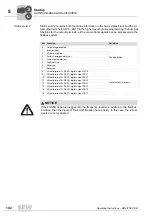
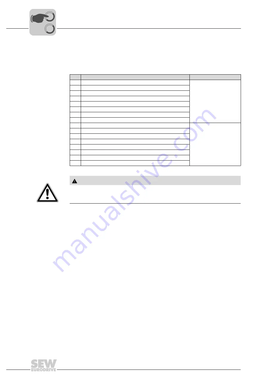
Status word 2
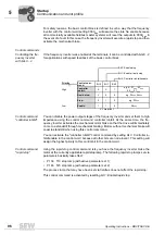
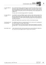
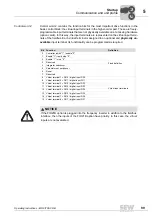
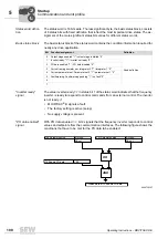
Status word 2 contains both the status information in the basis status block and the vir-
tual output terminals DO10 - DO17 in the higher-level byte. By programming the terminal
functions for the output terminals, all the conventional signals can be processed via the
fieldbus system.
Bit Function
Definition
0
Output stage enabled
Fixed definition
1
Inverter ready
2
PO data enabled
3
Current ramp generator set
4
Current parameter set
5
Fault/warning
6
Reserved
7
Reserved
8
Virtual terminal 1 = P630 / digital output DO10
Virtual output terminals
9
Virtual terminal 2 = P631 / digital output DO11
10
Virtual terminal 3 = P632 / digital output DO12
11
Virtual terminal 4 = P633 / digital output DO13
12
Virtual terminal 5 = P634 / digital output DO14
13
Virtual terminal 6 = P635 / digital output DO15
14
Virtual terminal 7 = P636 / digital output DO16
15
Virtual terminal 8 = P637 / digital output DO17
NOTICE
If the FIO21B option is plugged into the frequency inverter in addition to the fieldbus
interface, then the inputs of the FIO21B option have priority. In this case, the virtual
inputs are not evaluated.
00
I
Summary of Contents for Movitrac B
Page 2: ...SEW EURODRIVE Driving the world...
Page 259: ......

