Operating Instructions – MOVITRAC® B
105
5
Communication and unit profile
Startup
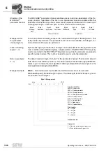
Timeout monitoring
is useful for all communciation interfaces. However, it may vary
considerably between the individual bus systems.
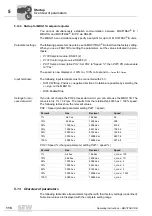
5.11.6 Setting the inverter parameters
The drive parameters of the inverter are usually accessed using the bus-specific READ
and WRITE services. Additional services can be executed for all bus system using the
MOVILINK
®
parameter channel. This parameter channel is available in all bus systems
and is explained in detail below.
Also refer to the documentation for the fieldbus interface to obtain additional program-
ming information on using the MOVILINK
®
parameter channel with the various bus sys-
tems.
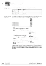
Parameter setting
procedure
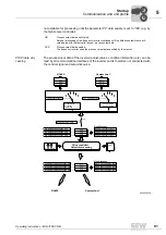
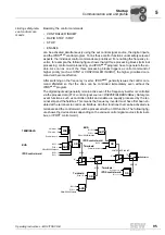
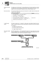
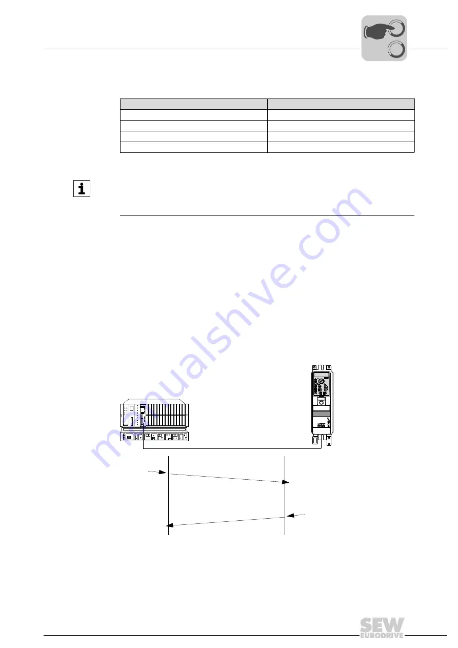
The parameters of the MOVITRAC
®
B frequency inverter are usually set based on a cli-
ent/server model. This means the frequency inverter provides the requested information
only when prompted by the higher-level programmable controller. This means that
MOVITRAC
®
B usually only has server functionality (see following figure).
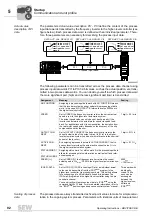
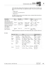
Parameters for fieldbus timeout
Value range
Unit
Seconds
Range
0.01 s to 650.00 s in 10 ms steps
Special case
0 or 650.00 = Fieldbus timeout deactivated
Factory setting
0.5 s
INFORMATION
With MOVILINK
®
via RS485 and SBus, the matching timeout interval must be set
manually in P812 or P883. For control via CANopen or FSE24B, the timeout interval
is automatically set in parameter P883.
5947102475
SERVER
CLIENT
Request
Indication
Response
Confirmation
00
I
Summary of Contents for Movitrac B
Page 2: ...SEW EURODRIVE Driving the world...
Page 259: ......

