182
Operating Instructions – MOVITRAC® B
8
Technical data for accessories and options
Technical data
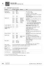
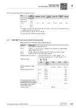
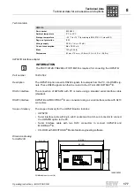
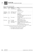
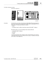
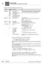
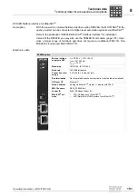
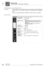
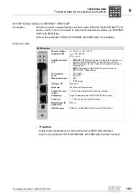
Electronics data FIO11B analog module
The terminal cross-section for all terminals of the FIO11B is:
• 1.5 mm
2
(AWG15) without conductor end sleeves
• 1.0 mm
2
(AWG17) with conductor end sleeves
Function
Terminal
Designation
Data
Setpoint input
1)
1) If you do not use the setpoint input you should connect it to GND. Otherwise a measured input voltage of –1 to +1 V is present.
X40:1
X40:2
AI2: Voltage input
GND: Reference potential
-10 to +10 V
R
i
> 40 k
Ω
Resolution 10 bit
Sampling time 5 ms
Accuracy ±100 mV, 200
μ
A
Analog output /
alternative as cur-
rent output or volt-
age output
X40:3
X40:4
X40:5
GND: Reference potential
AOV1: Voltage output
AOC1: Current output
0 – 10 V / I
max
= 2 mA
0 (4) – 20 mA
Resolution 10 bit
Sampling time 5 ms
Short-circuit proof, protected against external voltage up to 30 V
Load impedance R
L
≤
750
Ω
Accuracy ±100 mV, 200
μ
A
Service interface
X44
RJ10
Service interface
EIA standard, 9.6 kBd
Connection: Only for service purposes, solely for point-to-point
connection
Maximum cable length 3 m (10 ft)
RS485 interface
X45:H
X45:L
X45:
⬜
ST11: RS485+
ST12: RS485–
GND: Reference potential
EIA standard, 9.6 kBd, max. 32 stations
Maximum cable length 200 m (656 ft)
Dynamic terminating resistor with fixed installation
X44
RJ10
Service interface
Connection: Only for service purposes, solely for point-to-point
connection
Maximum cable length 3 m (10 ft)
X44 and X45 are connected in parallel in the FIO11B.
P
i
f
kVA
Hz
n
Summary of Contents for Movitrac B
Page 2: ...SEW EURODRIVE Driving the world...
Page 259: ......

