24
Operating Instructions – MOVITRAC® B
4
Installation notes for basic unit – electrical aspects
Installation
4.2.3
EMC-compliant installation
• Shield all cables except for the power supply cable. For the motor cable, you can use
the HD.. option (output choke) instead of the shielding to meet the interference emis-
sion limit values.
• When using shielded motor cables, e.g. prefabricated motor cables from SEW-
EURODRIVE, you must keep the unshielded conductors between the shield and
connection terminal of the inverter as short as possible.
• Connect the shield by the shortest possible route and make sure it is grounded over
a wide area at both ends. If using double-shielded cables, ground the outer shield on
the inverter end and the inner shield at the other end.
• You can also use grounded sheet-metal ducts or metal pipes to shield the cables.
Install the power and control cables separately.
• Provide high frequency compatible grounding for the inverter and all additional units
(wide area metal-on-metal contact between the unit housing and ground, e.g.
unpainted control cabinet mounting panel).
4.2.4
Shield terminals
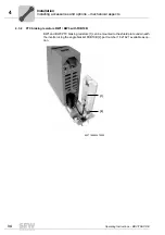
Installation of
shield plate for
control electronics
(all sizes)
MOVITRAC
®
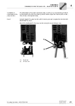
B includes a shield plate for the control electron-
ics with a retaining screw as standard. Install the shield plate for
control electronics as follows:
1. Loosen the screw first [1].
2. Insert the shield clamp into the slot in the plastic housing.
3. Fasten the shield clamp.
9007199272247947
INFORMATION
• MOVITRAC
®
B is a product that can cause electromagnetic interference according
to EN 61800-3. In this case, it is recommended for the operator to take suitable
measures.
• For detailed information on EMC-compliant installation, refer to the publication
"Drive Engineering – Practical Implementation: EMC in Drive Engineering" from
SEW-EURODRIVE.
[1]
Summary of Contents for Movitrac B
Page 2: ...SEW EURODRIVE Driving the world...
Page 259: ......

