Operating Instructions – MOVITRAC® B
87
5
Communication and unit profile
Startup
5.11.2 Process data configuration
The MOVITRAC
®
B frequency inverter can be controlled with 1 to 10 (with RS485 with
1 to 3) process data words via the communication interfaces. The number of process
input data (PI) and process output data (PO) is identical.
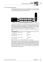
The process data configuration is set using DIP switches on the option card or via the
SBus master when starting up the bus system (e.g. PROFIBUS-DP or RS485). In this
way, the frequency inverter is automatically given the right setting. You can use the key-
pad or the MOVITOOLS
®
MotionStudio fieldbus monitor to check the current process
data configuration under the menu item
P090 Fieldbus PD configuration
.
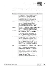
Depending on the fieldbus interface in use, the following process data configurations are
active:
Note
: 3 PD for bus cards, 10 PD for FSE24B of the front module type.
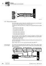
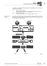
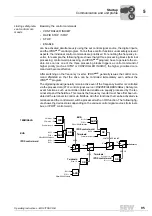
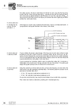
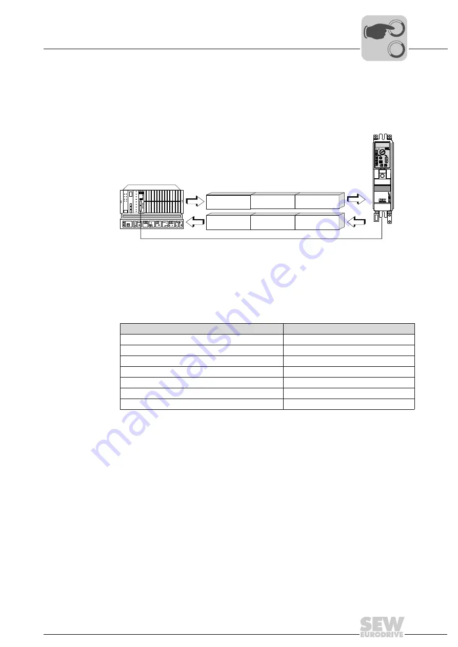
For process data control of the frequency inverter, only the number of process data is
relevant (that is 1PD - 10PD). These process data are usually mapped in the I/O or pe-
ripheral area when programmable logic controllers are used as fieldbus master. This
means the I/O or peripheral area of the PLC must provide sufficient memory space for
the process data of the frequency inverter (see following figure). The address between
process data of the frequency inverter and the PLC address area is usually assigned on
the fieldbus master interface module.
5945505675
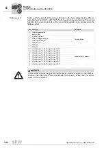
P090 PD configuration
1 process data word + parameter channel
1PD+PARAM
1 process data word
1PD
2 process data words + parameter channel
2PD+PARAM
2 process data words
2PD
....
....
10 process data words + parameter channel
10PD+PARAM
10 process data words
10PD
PA 1
PA 2
PA
PA 3
PE 1
PE 2
PE
PE 3
00
I
Summary of Contents for Movitrac B
Page 2: ...SEW EURODRIVE Driving the world...
Page 259: ......


