Operating Instructions – MOVITRAC® B
89
5
Communication and unit profile
Startup
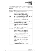
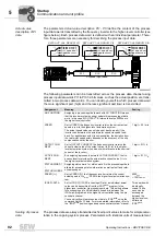
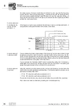
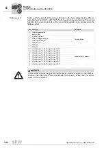
You can use the process output data words PO1, PO2 and PO3 to transmit the men-
tioned setpoints across the process output data channel. You can decide yourself in
which process data word the more significant part (high) or the less significant part (low)
is transmitted.
Assignment
Meaning
Scaling
NO FUNCTION
The setting
NO FUNCTION
has the effect that the frequency
inverter does not use this process output data word for processing
setpoints. The content of the process output data word pro-
grammed to
NO FUNCTION
is ignored although the controller
might specifiy a real setpoint via the fieldbus system.
The NO FUNCTION setting just disables the processing of the
process output data word in the inverter system. However, you
can access the process output data at any time using IPOS
plus®
.
SPEED
Set to
SPEED
, the MOVITRAC
®
B frequency inverter interprets
the setpoint value transmitted by this process data word to be the
speed setpoint if the selected operating mode (
P700 operating
mode 1
,
P701 operating mode 2
) allows a speed setpoint.
If there is no speed setpoint programmed although a communica-
tion interface (FIELDBUS, RS485, system bus) has been set as
setpoint source, the frequency inverter will use speed setpoint =
0.
1 digit = 0.2 / min
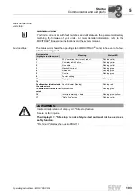
CURRENT
Set to
CURRENT
, the frequency inverter will interpret the setpoint
specified in this process data word as current setpoint if a variant
with torque control is set as operating mode (
P700 Operating
mode 1
). Else, the frequency inverter ignores the current setpoint.
1 digit = 0.1 % I
N
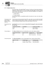
MAX. SPEED
Set to
MAX. SPEED
, the MOVITRAC
®
B frequency inverter inter-
prets the transmitted setpoint as speed limit. The speed limit is
specified in rpm and is interpreted as value for both directions of
rotation.
The supported value range of the speed limit via fieldbus corre-
sponds to the value range of parameter
P302 Maximum speed 1
.
Specifying the speed limit via fieldbus automatically disables
parameters
P302 Maximum speed 1, P312 maximum speed 2
.
1 digit = 0.2 / min
MAX. CURRENT
Set to
MAX. CURRENT
, the MOVITRAC
®
B frequency inverter
interprets the transmitted process output data as current limit. The
current limit is specified in percent with reference to the nominal
inverter current in the unit % I
N
. It is interpreted as value for both
directions of rotation.
The supported value range of the current limit via fieldbus corre-
sponds to the value range of parameter
P303 Current limit 1
. The
current limits that can be set using parameters
P303 Current limit
1
and
P313 Current limit 2
are still valid when the current limit is
specific using process data. This means these parameters are to
be regarded as maximum effective current limit.
1 digit = 0.1 % I
N
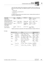
SLIP
Set to
SLIP
means the MOVITRAC
®
B frequency inverter inter-
prets the transmitted process output data word as slip compensa-
tion value.
Specifying the slip compensation via fieldbus automatically dis-
ables parameters
P324 Slip compensation 1
and
P334 Slip com-
pensation 2
.
Specifying the slip compensation via process data channel is only
technically meaningful in the
VFC N-CONTROL
operating mode
because the torque can be influenced directly by changing the slip
compensation.
The value range of this slip compensation value is identical with
the value range of parameter
P324 Slip compensation 1
and cor-
responds to a speed range of 0 - 500 rpm.
If the slip specified using process data is outside this value range,
the maximum will take effect when the minimum and maximum
values are exceeded.
1 digit = 0.2 / min
00
I
Summary of Contents for Movitrac B
Page 2: ...SEW EURODRIVE Driving the world...
Page 259: ......


