168
Operating Instructions – MOVITRAC® B
8
Technical data of the basic unit
Technical data
8.1.6
MOVITRAC
®
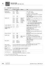
B electronics data
Function
Terminal Designa-
tion
Default
Data
Setpoint input
(differential input)
X10:1
X10:2
X10:3
X10:4
REF1
AI11 (+)
AI12 (–)
GND
+10 V, I
max
= 3 mA
0 – 10 V (R
i
> 200 k
Ω
)
0 – 20 mA / 4 – 20 mA (R
i
= 250
Ω
),
Resolution 10 bits, sampling cycle 1 ms, accuracy
±100 mV, 200
μ
A
GND = Reference potential for binary and analog
signals, PE potential
Digital inputs
X12:1
X12:2
1)
X12:3
X12:4
X12:5
X12.6
1) X12:2 / DI01 with fixed assignment CW/stop
DI00
DI01
DI02
DI03
DI04
DI05TF
Fault reset
CW/stop
CCW/stop
Enable/Stop
n11/n21
n12/n22
R
i
= 3 k
Ω
, I
E
= 10 mA, sampling time 5 ms, PLC
compatible
Signal level according to EN 61131-2 type 1 or 3:
•
11 – 30 V
→
1 / contact closed
•
–3 – +5 V
→
0 / contact open
•
X12:2 / DI01 with fixed assignment CW/halt
•
X12:5 / DI04 can be used as frequency input
•
X12:6 / DI05 can be used as TF input
Supply voltage for TF
X12:7
VOTF
Special characteristics for TF according to
DIN EN 60947-8 / trip value 3 k
Ω
Auxiliary voltage output
/external voltage
supply
2)
2) The MC07B...-S0 unit type must always be supplied with external voltage.
X12:8
24VIO
Auxiliary supply output: V = DC 24 V, current
carrying capacity I
max
= 50 mA
External voltage supply:
V = DC 24 V –15% / +20% according to
EN 61131-2
See chapter "Project planning / External DC 24 V
voltage supply".
Reference terminal
X12:9
GND
Reference potential for binary and analog signals,
PE potential
Digital outputs
X13:1
X13:2
X13:3
X13:4
GND
DO02
DO03
GND
Brake released
Ready
PLC compatible, response time 5 ms,
I
max
DO02 = 150 mA, I
max
DO03 = 50 mA,
short-circuit proof, protected against external volt-
age up to 30 V
GND = Reference potential for binary and analog
signals, PE potential
Relay output
X13:5
X13:6
X13:7
DO01-C
DO01-NO
DO01-NC
Shared relay contact
NO contact
NC contact
Load capacity: V
max
= 30 V, I
max
= 800 mA
Safety contact
See chapter "MOVITRAC
®
B electronics data for functional safety" (page 169).
Terminal response
times
Digital input and output terminals are updated every 5 ms
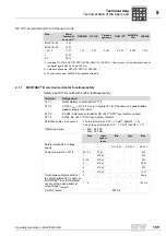
Max. cable cross-
section
1.5 mm
2
(AWG15) without conductor end sleeves
1.0 mm
2
(AWG17) with conductor end sleeves
Cable stripping length
X10 / X12 / X13: 5 mm
FSC11B/12B / FIO11B/21B / FSE24B: 7 mm
Tightening torque
X10 / X12 / X13: 0.25 Nm
FSC11B/12B / FIO11B/ 21B / FSE24B: 0.22 – 0.25 Nm
P
i
f
kVA
Hz
n
Summary of Contents for Movitrac B
Page 2: ...SEW EURODRIVE Driving the world...
Page 259: ......


