Operating Instructions – MOVITRAC® B
169
8
Technical data of the basic unit
Technical data
DC 24 V power demand for 24 V backup mode
8.1.7
MOVITRAC
®
B electronics data for functional safety
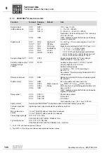
Safety input X17 for units with built-in functional safety:
Size
Power
demand of
basic unit
1)
1) Including FIO21B, FBG11B, FSC11B/12B (UWS11A / USB11A). Take account of the additional load of
the digital inputs with 2.4 W per 100 mA.
DBG60B
FIO11B
Fieldbus
option
2)3)
2) Fieldbus options are: DFP21B, DFD11B, DFE32B, ...
3) These options must ALWAYS be supplied externally.
DHP11B
DHE21B/4
FSE24B
0 MC07B..-00
5 W
1 W
2 W
3.4 W
4.5 W
8.5 W
1.2 W
0 MC07B..-S0
12 W
1, 2S, 2
17 W
3
23 W
4, 5
25 W
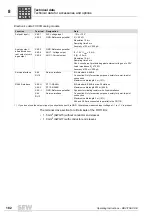
Terminal
Designation
X17:1
GND: Reference potential for X17:2
X17:2
VO24: V
OUT
= DC 24 V, only to supply X17:4 of the same unit;
must not be
used
to supply other units.
X17:3
SOV24: Reference potential for DC +24 V "STO" input (safety contact)
X17:4
SVI24: DC +24 V "STO" input (safety contact)
Permitted cable cross section
1 core per terminal: 0.75 – 1.5 mm
2
(AWG21 – 15)
Two cores per terminal: 0.75 – 1.0 mm
2
(AWG21 – 17)
Tightening torque
•
Min. 0.22 Nm
•
Max. 0.25 Nm
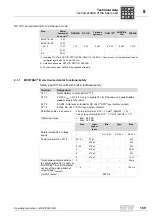
Size
Input
capaci-
tance
Min.
Type.
Max.
Safety-related 24 V voltage
supply
–
–
DC 19.2 V
DC 24 V
DC 30 V
Power consumption X17:4
0S / 0L
27 µF
–
–
3 W
1
270 µF
5 W
2 / 2S
270 µF
6 W
3
270 µF
7.5 W
4
270 µF
8 W
5
270 µF
10 W
Time between disconnection of
the safety-related 24 V supply at
MOVITRAC
®
B until the discon-
nection of the pulse pattern at
output stage t
switch-off
.
0
–
–
–
20 ms
1 – 5
–
–
–
100 ms
Time for restart
200 ms
P
i
f
kVA
Hz
n
Summary of Contents for Movitrac B
Page 2: ...SEW EURODRIVE Driving the world...
Page 259: ......

